Read the full article how to wire and set up the lcd module with the raspberry pi by raspberrypi-spy.co.uk.
The pinout of the lcd module is :
- Ground
- VCC (Usually +5V)
- Contrast adjustment (VO)
- Register Select (RS): RS=0: Command, RS=1: Data
- Read/Write (R/W): R/W=0: Write, R/W=1: Read
- Enable
- Bit 0 (Not required in 4-bit operation)
- Bit 1 (Not required in 4-bit operation)
- Bit 2 (Not required in 4-bit operation)
- Bit 3 (Not required in 4-bit operation)
- Bit 4
- Bit 5
- Bit 6
- Bit 7
- LED Backlight Anode (+)
- LED Backlight Cathode (-)
In the following picture the wiring is shown:
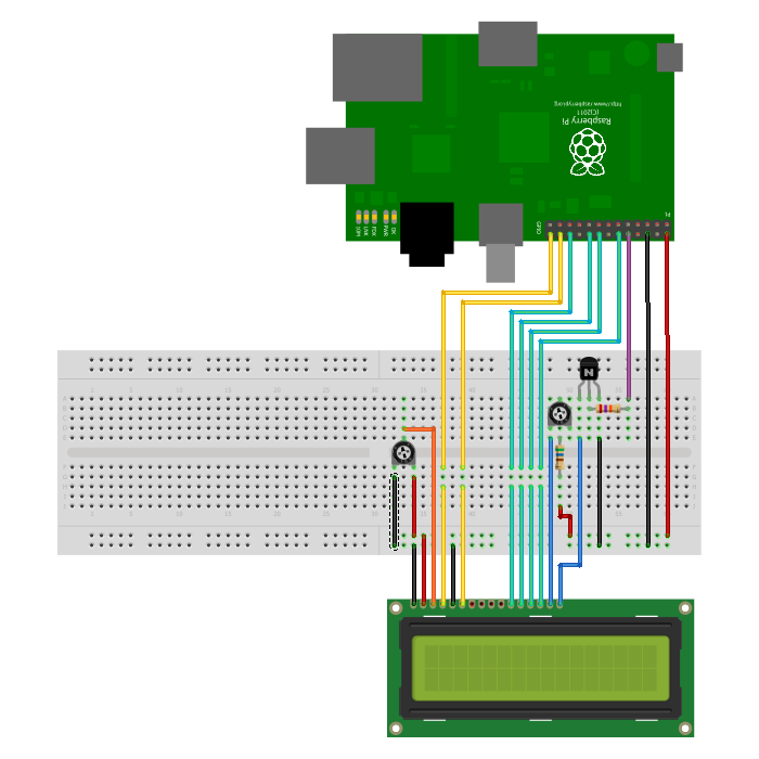
The following pins are connected in detail:
| LCD-Pin | Function | Pi-Function | Pi-Pin |
|---|---|---|---|
| 01 | GND | GND | P1-06 |
| 02 | +5V | +5V | P1-02 |
| 03 | Contrast | ||
| 04 | RS | GPIO7 | P1-26 |
| 05 | RW | GND | P1-06 |
| 06 | E | GPIO8 | P1-24 |
| 07 | Data 0 | ||
| 08 | Data 1 | ||
| 09 | Data 2 | ||
| 10 | Data 3 | ||
| 11 | Data 4 | GPIO25 | P1-22 |
| 12 | Data 5 | GPIO24 | P1-18 |
| 13 | Data 6 | GPIO23 | P1-16 |
| 14 | Data 7 | GPIO18 | P1-12 |
| 15 | +5V via 560 ohm | ||
| 16 | GND | P1-06 |