City Power & Light is a sample application that allows citizens to report "incidents" that have occurred in their community. It includes a landing screen, a dashboard, and a form for reporting new incidents with an optional photo. The application is implemented with several components:
- Front end web application contains the user interface and business logic. This component has been implemented three times in .NET, NodeJS, and Java.
- WebAPI is shared across the front ends and exposes the backend CosmosDB.
- CosmosDB is used as the data persistence layer.
In this lab, you will combine the web app with an IoT device based on an Arduino-compatible board that will query the app for the number of incidents and display the refreshed number every minute.
In this hands-on lab, you will learn how to:
- Set up the developing environment to support the programming of Arduino chips.
- Create your own IoT software from scratch.
- The source for the starter app is located in the start folder.
- The finished project is located in the end folder.
- Deployed the starter ARM Template HOL 1.
- Completion of the HOL 5.
This hands-on-lab has the following exercises:
- Exercise 1: Set up your environment
- Exercise 2: Create output that will be consumed by the device
- Exercise 3: Program the device
To program an Arduino device on your machine you need the Arduino IDE and Visual Studio on your machine. Since a hardware connection to the device is required this will not work from a virtual machine. It is possible to use an Arduino emulator for this lab instead of the actual device and work through the exercises in a virtual machine.
You will now install the Arduino IDE and setup the board manager.
-
Download the Arduino IDE package from the Arduino download page. Go to www.arduino.cc/en/Main/Software and select the
Windows installer. The Windows installer sets up everything you need to use the Arduino IDE. If you use the ZIP file you need to install the drivers manually. The drivers are located here: https://github.com/nodemcu/nodemcu-devkit/tree/master/Drivers.
-
Run the installer and accept the license agreement.
-
Select the components to install. Keep at least
Install USB driverselected.
-
Select the installation folder. You should keep the default destination folder.

-
After setup completed close the window and run Arduino.

-
Arduino should look like this:

-
Select
File->Preferences.
-
Locate the
Additional Boards Manager URLsproperty and enter the URLhttp://arduino.esp8266.com/stable/package_esp8266com_index.jsonand clickOK.
-
Select
Tools->Board->Boards Manager....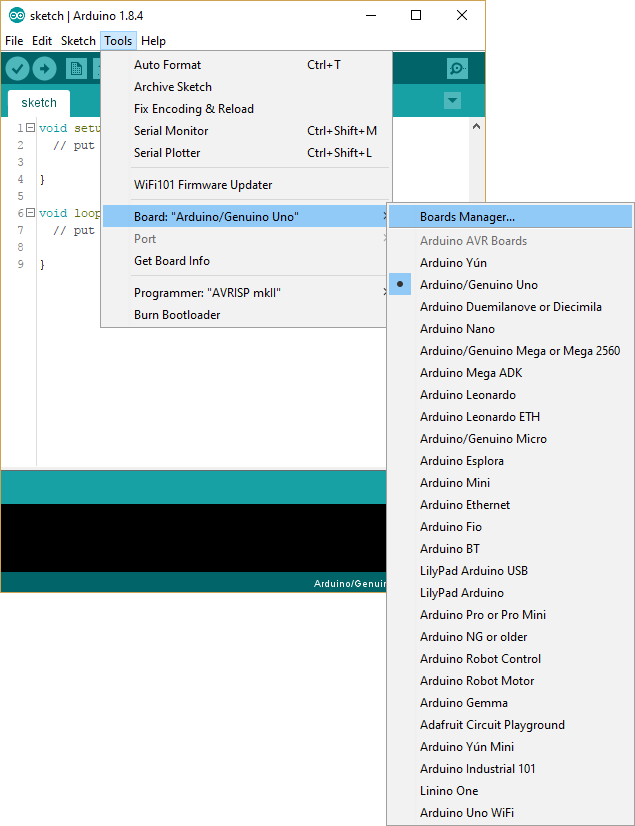
-
In the
Boards Managerdialog enteresp8266into the search field. The Arduino packageesp8266will appear. Select the latest version and clickInstallto download and install the package.
-
After the installation completed, click
Close.
-
Select the board from the list of boards by clicking
Tools->Board->NodeMCU 1.0 (ESP-12E Module).
-
Set the port by selecting the correct COM port from
Tools->Port->Serial ports. Also make sureUpload Speed: "115200"is selected.


You have now installed all the necessary components to start programming an Arduino device on your machine.
The device will regularly call an URL to fetch the current incident count. We will add a page to our existing web application as an easy way to provide this data.
-
In the
DevcampApplication.javafile add/IoT**to the list ofantMatchers. -
Create a new Controller. Right-click on
devCamp.WebApp.Controllersand selectNew->Class.
-
In the
New Java Classdialog enterIoTControlleras the name and clickFinish.
-
The controller will just emulate the behavior of the dashboard controller. Add the following code to the newly created file:
package devCamp.WebApp.Controllers;

import java.util.List;
import java.util.concurrent.CompletableFuture;

import devCamp.WebApp.models.IncidentBean;
import devCamp.WebApp.services.IncidentService;
import org.slf4j.Logger;
import org.slf4j.LoggerFactory;
import org.springframework.beans.factory.annotation.Autowired;
import org.springframework.scheduling.annotation.Async;
import org.springframework.stereotype.Controller;
import org.springframework.ui.Model;
    import org.springframework.web.bind.annotation.RequestMapping;

@Controller
public class IoTController {
  private static final Logger LOG = LoggerFactory.getLogger(DashboardController.class);

  @Autowired
  IncidentService service;

  @RequestMapping("/IoT")
  public String iot(Model model) {
    List<IncidentBean> list = service.getAllIncidents();
    model.addAttribute("allIncidents", list);
    return "IoT/index";
  }
}
-
Create a new template. Right-click on
src/main/resourcesand selectNew->Other.... ...
-
In the
Newdialog select theHTML Filetemplate and clickNext >.
-
Set the folder to
[...]/resources/templates/IoTand the file name toindex.html, then clickFinish.
-
The template will only display the number of incidents. Add the following code to the newly created file:
IncidentCount=<span th:text="${allIncidents.size()}" th:remove="tag"></span>
-
Start the debugger and add
/IoTto the URL to test the new view. It will contain just the number of incidents.
-
Publish the changes to your Azure web app and make sure the
/IoTURL is reachable (see HOL 5).


You have now created the data feed for your device.
The Arduino-compatible device can handle data exchange with web applications. At first we will connect the device to a Wi-Fi, and then we will add an HTTP request to retrieve the amount of incidents from the web application.
It is important to develop projects in small chunks and to understand and test each function. Try to develop code with small functions that clearly separate the functionalities of your device and combine them step by step.
-
Make sure the device is connected to your USB port and open Arduino and create a new sketch.
-
Replace the sketch content with the following code which will connect the device to a specified wireless network. Replace the SSID and the password with proper values.
#include <ESP8266WiFi.h>

// Pins
#define LED_PIN   D4 // build-in LED in NodeMCU

// Wifi
char* ssid = "***";
char* password = "***";

void setup() {
  Serial.begin(115200); // sets up serial data transmission for status information

  pinMode(LED_PIN, OUTPUT);

  connectWifi(ssid, password);
}

void loop() {
  if (WiFi.status() != WL_CONNECTED) {
    digitalWrite(LED_PIN, HIGH); // turn the LED off
  } else {
    delay(250);
    digitalWrite(LED_PIN, LOW);
    delay(50);
    digitalWrite(LED_PIN, HIGH);
  }
}

void connectWifi(char* ssid, char* password) {
  Serial.print("Connecting to Wi-Fi");

  WiFi.hostname("NodeMCU@DevCamp");
  WiFi.begin(ssid, password);

  uint8_t i = 0;
  while (WiFi.status() != WL_CONNECTED && i++ < 50) {
    Serial.print(".");
    delay(500);
  }
  Serial.println(".");

  if (WiFi.status() != WL_CONNECTED) {
    Serial.println("Could not connect to Wi-Fi");
  } else {
    Serial.print("Connected to Wi-Fi: ");
    Serial.println(ssid);
    Serial.print("IP address: ");
    Serial.println(WiFi.localIP());
  }
}
-
When it comes to debugging code in Arduino,
Serial.print()andSerial.println()are the best way to go.Serial.begin(115200);sets up serial data transmission with 115200 baud. SelectTools->Serial Monitorto open theSerial Monitordialog for the selected COM port.
-
In the
Serial Monitordialog select115200 baudfrom the list and leave the dialog open to see the output from the device.
-
Let's test the wireless network connection. Hit
CTRL+Uto compile and upload the sketch to your device. Confirm if you are asked to save the code in a local file. You can follow the upload process in the status window at the bottom. If the upload fails and you have multiple COM ports try selecting the other ports. -
If the connection to your network was established, the LED on your device will start blinking. It will completely turn off if the connection has failed. The COM monitor window will also display the connection attempts made by the device.

-
Now we will add an HTTP request to our Arduino code. The new code will also add the method
getIncidentCount()which will fetch the current incident count from theIoTview created inExercise 2. Use the code below to replace or adapt the existing code.#include <ESP8266WiFi.h> // Pins #define LED_PIN D4 // build-in LED in NodeMCU // Wifi char* ssid = "***"; char* password = "***"; // Request const int port = 80; const char* server = "<app_name>.azurewebsites.net/IoT"; // address for request, without http:// const char* searchString = "IncidentCount="; // search for this property void setup() { Serial.begin(115200); // sets up serial data transmission for status information pinMode(LED_PIN, OUTPUT); connectWifi(ssid, password); } void loop() { if (WiFi.status() != WL_CONNECTED) { digitalWrite(LED_PIN, HIGH); } else { // retrieve the amount of incidents int incidentCount = getIncidentCount(); // keep the led blinking for the amount of incidents for (int i = 0; i < incidentCount; i++) { delay(250); digitalWrite(LED_PIN, LOW); delay(50); digitalWrite(LED_PIN, HIGH); } // pause between requests delay(60000); } } void connectWifi(char* ssid, char* password) { Serial.print("Connecting to Wi-Fi"); WiFi.hostname("NodeMCU@DevCamp"); WiFi.begin(ssid, password); uint8_t i = 0; while (WiFi.status() != WL_CONNECTED && i++ < 50) { Serial.print("."); delay(500); } Serial.println("."); if (WiFi.status() != WL_CONNECTED) { Serial.println("Could not connect to Wi-Fi"); } else { Serial.print("Connected to Wi-Fi: "); Serial.println(ssid); Serial.print("IP address: "); Serial.println(WiFi.localIP()); } } int getIncidentCount() { WiFiClient client; if (client.connect(server, port)) { Serial.print("Connected to "); Serial.println(server); Serial.println("Sending request"); client.print("GET /"); client.println(" HTTP/1.1"); client.print("Host: "); client.print(server); client.print(":"); client.println(port); client.println("Connection: close"); client.println("Accept: text/html"); client.println(); // waiting for server response... while (client.connected()) { // ...until the response is available if (client.available()) { // looking for search string in response data if (client.findUntil(searchString, "\0")) { int result = client.readStringUntil('\n').toInt(); Serial.print(searchString); Serial.print("="); Serial.println(result); return result; } } } client.stop(); Serial.println(); Serial.println("Connection closed"); } else { Serial.print("Connection to "); Serial.print(server); Serial.println(" failed"); } return 0; }
-
Replace the SSID and the password with proper values. Also replace the address in the following line with the address to the
IoTview:const char* server = "<app_name>.azurewebsites.net/IoT"; // address for request, without http://
-
Select
Sketch->Uploador useCTRL+Uto compile and upload the sketch to your device. The device will retrieve the amount of incidents from theIoTview and flash the LED for this amount. Again you can use the COM monitor to follow the progress of the code execution on the device.


This example shows how to work with data requests, how to link the device to a data source on the internet and display the state using a simple LED.
In this hands-on lab, you learned how to:
- Set up the developing environment to support the programming of Arduino chips.
- Create your own IoT software from scratch.
After completing this module, you can continue on to the Stretch Goal.
View Stretch Goal instructions for Java
Copyright 2017 Microsoft Corporation. All rights reserved. Except where otherwise noted, these materials are licensed under the terms of the MIT License. You may use them according to the license as is most appropriate for your project. The terms of this license can be found at https://opensource.org/licenses/MIT.