Process workflow
This page is written for the developer who wants to contribute to this code, or wants to remember what he did some years ago. Many hints can be found in the code comments, but some parts of the process flow need a deeper description and/or drawings to be understood.
The arguments of the interface of polygonize() can be found in its documentation. A preprocessing part creates a Python list edgeContours of all the shapes (outer contour and holes) needed for skeletonization and graph construction. The outer contour edges2D and the edges holeEdges of the holes are Python lists of the Edge2 class, defined in bpyeuclid.py. The 2D center of gravity centerof all vertices in verts is used to normalize them. It is subtracted from each vertex in the constructor of Edge2.
The list edgeContours with all shapes (outer contour and holes) is the only argument passed to the function skeletonize(). This function returns the straight skeleton of the footprint described in edgeContours and its process flow is described below. skeletonize() returns the skeleton as a list of subtrees (of type Subtree) of the straight skeleton. A Subtree contains the attributes (source, height, sinks), where source is the node vertex, height is its distance to the nearest polygon edge, and sinks is a list of vertices connected to the node.
In a next step, the heights of all skeleton nodes are computed, based on the input arguments height and tan of polygonize(). This computation is described in issue #4 of the repo. Then the Python list verts, also an input argument, is extended by these nodes.
A graph with all nodes (original vertices of the outer contour, holes and skeleton nodes) and their egdes is constructed in the class poly2FacesGraph, defined in poly2FacesGraph.py. The nodes are stored as their index in the extended vertex list verts and the edges as tuples of the these indices. Special attention must be paid to whether the sinks of the skeleton Subtrees are polygon vertices or skeleton nodes. The neighbors of each node in the graph must be sorted by their angles to allow counter-clockwise ordering of the edges. The function circular_embedding() in poly2FacesGraph constructs this embedding.
The extraction of the faces in the method faces() starts with the collection of all edges in a set of egdes. Similar to half-edge graphs, each edge is stored in a forward and backward direction. Then, starting with any edge in this set, its counter-clockwise neighbor is found and added to a path, while this edge is removed from the set. When the initial edge is reached again, a face has been found and can be added to the list of faces. This process is repeated until there are no more edges in the edge set.
Finally, some post-processing is required. If one of the vertices of a face is an original vertex of the outer contour or one of the holes, the order in the face is rotated, so that such a vertex becomes the first index in the face. Faces, that are actually the perimeter or one of the holes are eliminated. The final list of faces is returned to faces3D in polygonize().
Sometimes, the skeletonization algorithm returns edges, that result in a spike in a face. Such spikes may appear in two flavors, depending on the order in which the faces are tested, they can point to the outside of the face or to the inside of the face:


Spikes are characterized by a sharp turn of nearly 180° of adjacent edges to the left or to the right. This can be detected using the dot-product and the cross-product of the two vectors along these edges. The dot product gives the cosine of the angle and must be close to -1, while the cross product gives the sine of the angle and must be close to zero.
The two flavors shown above are distinguished by looking at the two faces at the right of the two spike vectors. When both are identical (the face under test), the case shown in the right image is found. Removing the spike vertex and one of its neighbors removes the spike for this case. The other case is more complicated:
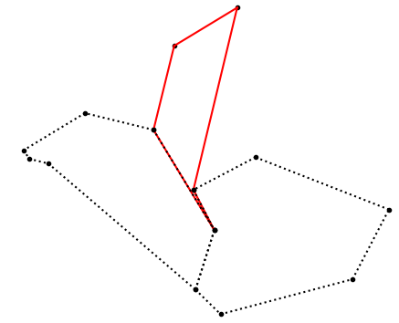

The test face (red in the left image) is corrected by removing the spike vertex. The leaning faces (dotted) become one single face (see right image) by removing the spike vertex in both faces and merging them.
The process of spike removal is repeated until no more spikes are found.
The basic data structure used by the algorithm is a set of circular lists of active vertices (SLAV). This structure stores a loop of vertices for outer boundary and for all holes and sub-polygons created during the straight skeleton computation. The basic elements of these lists are the classes _LAVertex and _LAV. The first is the container element of the double-linked list, the node. It contains the pointers to the previous and the next nodes. The latter holds the anchors of one such list. Both contain many additional methods, which will be discussed in detail during this description.
In a first step such lists _LAV are constructed for the perimeter of the polygon and, if available, for each hole. All of them are collected in a list within the class SLAV. All these contours are additionally stored in the argument _original_edges, which is a list of instances of _OriginalEdge. While the instances in _LAV are changed during the process, these original edges remain constant.
A special shape that we called dormer required special detection and processing. Four vertices with a sequence of right - left - left - right turns (RLLR ) in counterclockwise order by angles of almost 90° form such a dormer (left image below). The normal algorithm, as described by the paper by Felkel and Obdržálek, creates so called ghost edges (the red line in the right image) from such shapes.


All initial events are created by the vertices (_LAVertex). These can be edge events (_EdgeEvent) or split events (_SplitEvent), or later from dormer processing, dormer events (DormerEvent). The first two are created by the next_event() method of _LAVertex, the latter during processing of dormers. Among other information, all these events have a distance argument, which is the distance of the event (a point) to the nearest edge. All these events are put into a priority queue (class _EventQueue), which sorts them by increasing distance. This completes the initialization for the "algorithm for non-convex polygons".
The next action is to execute the processing loop, which runs until there are no more events in the event queue. The event with the highest priority (shortest distance) is extracted from the queue. If several events have the same distance, they are all extracted and processed, before the next extraction takes place. Depending on the event type, the appropriate event handler of SLAV is called for the event. It will eventually return one or more skeleton arcs and new events. The arcs are added to the output list, while the new events are added to the priority queue. Skeleton arcs are instances of Subtree. A Subtree contains the attributes (source, height, sinks), where source is the node vertex, height is its distance to the nearest polygon edge, and sinks is a list of vertices connected to the node.
Finally, as a sort of post-processing, node clusters of arcs are merged, and nearly parallel egdes are removed. Node clusters of arcs are groups of arcs with identical or nearly identical source. Due to floating-point imprecision it is possible, that skeleton edges are created that are almost parallel or even intersect each other. All these cases are resolved and cleaned up here.