-
Notifications
You must be signed in to change notification settings - Fork 171
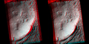
HiRISE_Anaglyphs
HiRISE Anaglyphs 
Using Stereo Observations: RED CCD[0-9]
Note : This anaglyph procedure is recommended for lowerlatitude
coverage; Polar region stereo coverage is more complicated and has not
been ‘stream-
lined’ yet.
Preparation - SPICE 
- Select two stereo observations
- Begin with calibrated images
- Geometric control is an option (ccd-to-ccd)
- Run spiceinit on all RED CCD’s0-9 for both observations
- Default to system shape model
- Kernels Group with loaded SPICE keywords
 Group = Kernels
  NaifIkCode = -74699
  LeapSecond = $base/kernels/lsk/naif0008.tls
  TargetAttitudeShape = $base/kernels/pck/pck00008.tpc
  TargetPosition = Table
  InstrumentPointing = Table
  Instrument = Null
  SpacecraftClock = $mro/kernels/sclk/MRO_SCLKSCET.00021.65536.tsc
  InstrumentPosition = Table
  Frame = $mro/kernels/fk/mro_v08.tf
  InstrumentAddendum = $mro/kernels/iak/hiriseAddendum003.ti
  ShapeModel = $base/dems/molaMarsPlanetaryRadius0001.cub
 End_Group
Run spicefit on all Red CCD’s 0-9 for both image observations 
- spicefit from=psp_red0.cub...
- Take ‘an’ approach to figure out the map information
 maptemplate fromlist=img1_0-9.lis map=img1.map proj=EQUIRECTANGULAR clat=0.0 clon=0.0 rngopt=CALC resop=CALC
 maptemplate fromlist=img2_0-9.lis map=img2.map proj=EQUIRECTANGULAR clat=0.0 clon=0.0 rngopt=CALC resop=CALC
- Evaluate the information within img1.map and img2.map
- Figure out the map values that will satisfy the coverage of both
observations
- latitude range, longitude rangecenter latitude, center longitude
- average pixel resolution
Retrieve the “local radius” 
- The default system shape model will be referenced (spiceinit)
- Specify the center of each observation
 campt from=psp_red5_img1.cub samp=1 line=(nlines/2) to=red5_pt1.dat

 getkey from=red5_pt1.dat grpnname=GroundPointkeyword=LocalRadius

 campt from=psp_red5_img2.cub samp=1 line=(nlines/2) to=red5_pt2.dat

 getkey from=red5_pt2.dat grpname=GroundPointkeyword=LocalRadius
- Calculate the average “local radius” value
- Convert the average value from meters to kilometers
- Build a NAIF-format text file with the average local radius (km)
- “LocalRad3391.97.tpc”contents
 \begindata
 BODY499_RADII       = ( 3391.97   3391.97 3391.97)
Modify Labels 
- For both observations; all Red CCD’s0-9
- Remove ShapeModel reference from labels
editlab from=psp_red0_img1.cub options=modkeygrpname=Kernels keyword=ShapeModel value=Null
- Now add the “new” NAIF .tpcfile with the local radius to the Kernels group
editlab from=psp_red0_img1.cub options=modkeygrpname=Kernels keyword=Instrument keyvalue= LocalRad3391.97.tpc
- Note : We are temporarily using an ‘unused’ keyword (Instrument) for the local radius .tpcfile; this keyword follows the main “TargetAttitudeShape”keyword which MUST retain reference to the original NAIF .tpcfile (we are mimicking a ‘search’ list for radius value).
Kernels Group with modified keywords 
 Group = Kernels
  NaifIkCode = -74699
  LeapSecond = $base/kernels/lsk/naif0008.tls
  TargetAttitudeShape = $base/kernels/pck/pck00008.tpc
  TargetPosition = Table
  InstrumentPointing = Table
  Instrument          = LocalRad3386.70.tpc
  SpacecraftClock = $mro/kernels/sclk/MRO_SCLKSCET.00021.65536.tsc
  InstrumentPosition = Table
  Frame               = $mro/kernels/fk/mro_v08.tf
  InstrumentAddendum = $mro/kernels/iak/hiriseAddendum003.ti
  ShapeModel = Null
 End_Group
-

Local Radius retains both high and low frequency stereo data -

Low frequency stereo information is removed; (e.g., gentle slopes across the scene)

Map Projection - Template 
- Build a Map Template for cam2map
- Specify the Ellipsoid values for Mars Contents:
 ::::::::::::::
 equi.map
 ::::::::::::::
 Group = Mapping
  ProjectionName = Equirectangular
  CenterLongitude = 353.18
  CenterLatitude = 8.06
  TargetName = mars
  EquatorialRadius = 3396190.0 <meters>
  PolarRadius = 3376200.0 <meters>
  LatitudeType = Planetocentric
  LongitudeDirection = PositiveEast
  LongitudeDomain = 360
  PixelResolution = 0.28 <meters/pixel>
 End_Group
 End
Map Projection 
- Run
cam2map
on both observations
- all Red ccd’s[0-9]
cam2map from=psp_red0_img1.cub map=equi.mapto=psp_red0_eq.cub pixres=map defaultrange=camera
- OR Use the -batchlist option
cam2map –batchlist=all_reds.lis from=\$1.balance.cub to=\$1.eq.cub pixres=map defaultrange=camera
- all_reds.lis should not include file extensions
- Allow cam2map to figure out the lat/lon boundaries of each individual ccd
Create Two Red[0-9] Mosaics 
- Create a list of cam2map output files for each observation
- Mosaic the projected Red CCD’s
- Specify the same latitude/longitude boundaries for the output mosaics
 automos fromlist=img1_eq.lis mosaic=img1_RedMos.cub grange=user minlat=  maxlat=  minlon=  maxlon=
 automos fromlist=img2_eq.lis mosaic=img2_RedMos.cub grange=user minlat=  maxlat=  minlon=  maxlon=
- Refer to the camptoutput files that was executed previously
 getkey from=red5_pt1.dat grpnname=GroundPointkeyword=SubSpacecraftLongitude
 getkey from=red5_pt2.dat grpnname=GroundPointkeyword=SubSpacecraftLongitude
- The observation image whose SubspacecraftLongitude is the farthest
West, is the “Left Look”
- (subspc1 < subspc2) or (subspc2 < subspc1)
Assumptions 
- Observation pair has a longitude range within 0 –360 longitude
- LongitudeDomain= 360
- Neither image pair crosses the 0 and/or the 360 longitude boundary
- cam2map defaults to reassigning the LongitudeDomain if the image crosses a 0/360/180 boundary
Stack Left/Right Observations 
- Create a text file for cubeit
 ls left_redmos_img.cub > c.lis
 ls right_redmos_img.cub >> c.lis
- cubeit list=c.lis to=anag.cub
- Display anag.cub with qview
 Band1 = Red
 Band2 = Green
 Band2 = Blue
Local_Radius_bad_example.png View (436 KB) Ian Humphrey, 2016-05-31 04:22 PM
Hirise_stereo_information_removed.png View (258 KB) Ian Humphrey, 2016-05-31 04:22 PM
Hirise_low_freq_removed_gentle_slopes.png View (377 KB) Ian Humphrey, 2016-05-31 04:22 PM
Hirise_local_radius_both_high_and_low.png View (829 KB) Ian Humphrey, 2016-05-31 04:22 PM
Gullies_MOLA_Stereo_Profile.png View (123 KB) Ian Humphrey, 2016-05-31 04:23 PM
- Building
- Writing Tests
- Test Data
- Start Contributing
- Public Release Process
- Continuous Integration
- Updating Application Documentation
- Deprecating Functionality
- LTS Release Process and Support
- RFC1 - Documentation Delivery
- RFC2 - ISIS3 Release Policy
- RFC3 - SPICE Modularization
- RFC3 - Impact on Application Users
- RFC4 - Migration of ISIS Data to GitHub - Updated Information 2020-03-16
- RFC5 - Remove old LRO LOLA/GRAIL SPK files
- RFC6 - BLOB Redesign
- Introduction to ISIS
- Locating and Ingesting Image Data
- ISIS Cube Format
- Understanding Bit Types
- Core Base and Multiplier
- Special Pixels
- FAQ

