-
Notifications
You must be signed in to change notification settings - Fork 11
Architecture design

The above figure is a simple deployment architecture diagram. The following is a brief explanation of the diagram:
- A Reader cluster consists of multiple Reader service instances, which are generally deployed across computer rooms. All Reader service instances in a Reader cluster are exactly the same. The purpose of multiple instances is mainly for disaster recovery and stress load balancing.
- A Reader task only pulls the binlog of one MySQL cluster instance, so the corresponding relationship between the Reader task and the MySQL cluster is one-to-one. The Reader task defaults to pulling the binlog from the library. Regarding whether the reading of binlog by the Reader service will affect the slave library or the main library, the official conclusion given by the DBA is that the impact is negligible.
- A Reader service instance can have multiple Reader tasks, so the correspondence between Reader clusters and MySQL clusters is a 1-to-N relationship.
- An SDK cluster consists of multiple Writer service instances, which are generally deployed across computer rooms. The number of shards for each SDK task will be evenly distributed to each instance in the cluster.
- Implemented the MySQL Replication protocol, disguised as a MySQL Slaver, and pulled MySQL's binlog.
- Manage the table structure (hereinafter referred to as: Schema), parse and cache the binlog according to the Schema structure (supports both disk and memory cache modes).
- Manage the link with the SDK, and send the binlog of the specified site to the SDK according to the subscription site of the SDK (ProtoBuf encoding is used to send the binlog data by default).
- A Reader service can accommodate multiple Reader tasks, and a Reader task is associated with a database cluster.
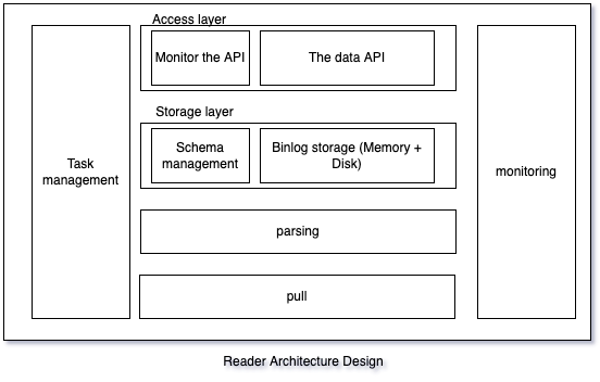
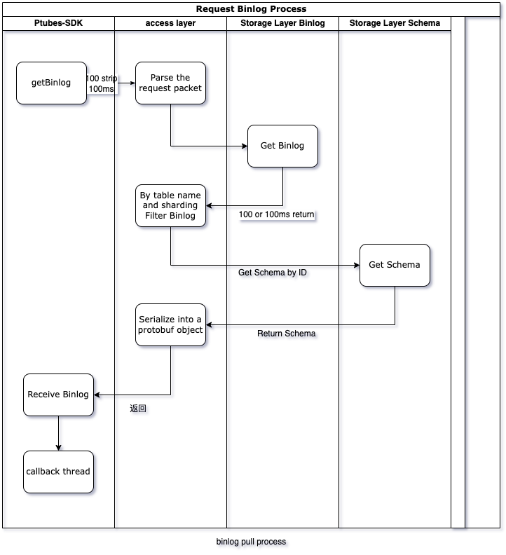
Ptubes storage layer is divided into two parts, memory storage and file storage
RAM
Use off-heap memory to store data, you can configure the size used by different tasks; use on-heap memory to store indexes.
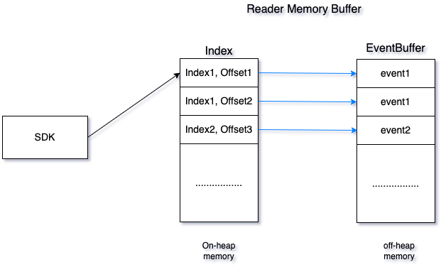
The cache consists of Index and EventBuffer. Both index and eventBuffer are implemented based on PtubesEventBuffer and support efficient reading and writing;
The Index stores the index of each block in the EventBuffer. After the data is written to the EventBuffer, the Index will be updated. When addressing, the block where the data is located will first be located in the Index (to improve the efficiency of finding points, the dichotomy method is used to find points. ), then traverse all the data of the corresponding block in the EventBuffer, and return the data to the SDK according to the storage point and fragmentation information requested by the SDK
Since Ptubes supports time, binlog position and gtid addressing, the Index structure is as follows:

File Storage
File Storage Structure
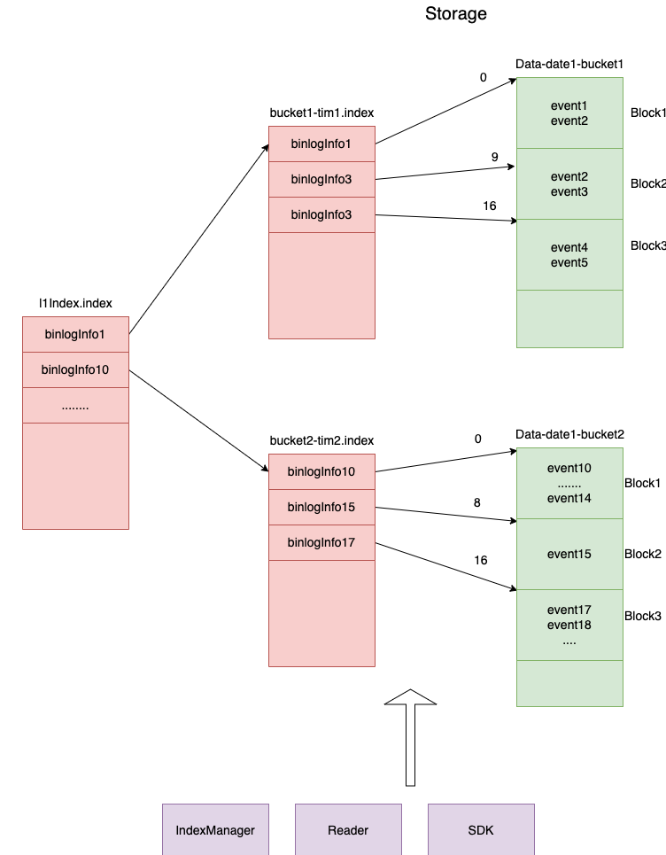
The file tree diagram is as follows
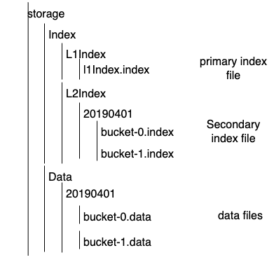
Storage Data Structure
BinlogInfo: used to uniquely mark the binlog information of an event, the key value in the index file
| Field Name | length(byte) | Meaning |
|---|---|---|
| changeId | 2 | The initial value is 0. Every time a database is cut, changeId+1 is used to ensure that the index is still incremented after the database is cut |
| serverId | 4 | serverId of the slave library |
| binlogFile | 4 | Number of binlog file from library |
| binlogOffset | 8 | Offset in binlog file |
| uuid | 16 | uuid of the gtid of the current transaction |
| transactionId | 8 | transactionId of the gtid of the current transaction |
| eventIndex | 8 | The index of the current event in the transaction |
| timestamp | 8 | binlog timestamp |
CheckPoint: The information used in the SDK to uniquely mark an event
| Field Name | length(byte) | Meaning |
|---|---|---|
| serverId | 4 | serverId of the slave library |
| binlogFile | 4 | Number of binlog file from library |
| binlogOffset | 8 | Offset in binlog file |
| uuid | 16 | uuid of the gtid of the current transaction |
| transactionId | 8 | transactionId of the gtid of the current transaction |
| eventIndex | 8 | The index of the current event in the transaction |
| timestamp | 8 | binlog timestamp |
DataPosition structure: used to identify the file and location where index or data is located
| Field Name | length(bit) | Meaning |
|---|---|---|
| date | 18 | binlog date |
| bucketNumber | 14 | |
| offset | 32 | data or index file offset |
MaxBinlogInfo file: The storage layer is used to store the location where the binlog is pulled. When reconnecting or restarting the service, the binlog will continue to be pulled from this location and refreshed regularly.
//Contain all fields of BinlogInfo
serverId=slaveServerId,
binlogFile=2, //The initial value must be accurate
binlogOffset=774007788,//The initial value can be set to 4
binlogTime=2018-12-25 17:51:13,
refreshTime=2018-12-25 17:51:13,
gtid=ec4dafec-8a5b-11e8-81dc-00221358a93e:949976,
gtidSet=ec4dafec-8a5b-11e8-81dc-00221358a93e:1-963237
ChangeIdInfo file: store the changeId and the binlog starting location information of the corresponding slave library. When the service starts, check whether the serverId is the same as the last time. If it is different, append a changeId and save it, otherwise do not change it.
changeId=XX,serverId=XXX,gtidSet=XXXX,beginBinlogFile=XXX,beginBinlogOffset=XXX
changeId=XX,serverId=XXX,gtidSet=XXXX,beginBinlogFile=XXX,beginBinlogOffset=XXX
changeId=XX,serverId=XXX,gtidSet=XXXX,beginBinlogFile=XXX,beginBinlogOffset=XXX
The files are stored in hours by time path, each Data bucket is 1G, L2Index bucket and Data bucket are one-to-many relationship
L1Index File Structure

L2Index File Structure

Data file structure

L1Index file name: l1Index.index
L2Index file name: bucket-serial number.index
data file name: bucket-serial number.data
Read and write process
Write Process
When the EventProducer thread processes the event storage, it updates the cache and file at the same time
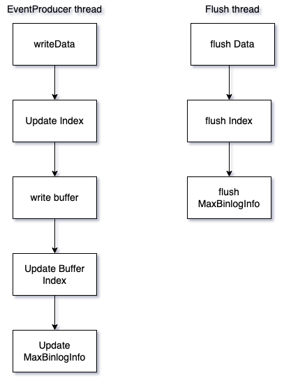
Write files using DataOutputStream, write data to the buffer area, and flush them asynchronously.
EventProducer thread: responsible for updating Buffer, file and Index
Flush thread: responsible for regular Flush Data files and Index files
CleanUp thread: responsible for regularly cleaning Data files and Index files
Flush conditions:
- Create a new bucket
- Finish writing a block
- Regular flush
- Flush when the program exits
Reading process
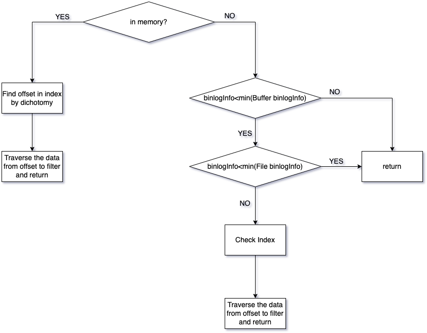
Addressing according to the binlogInfo brought by the SDK request
- Determine whether the data is in memory according to the memory buffer binlogInfo range. If it is in memory, go to step 2. If the found binlogInfo is less than the minimum binlogInfo of the memory, go to step 4. If it is greater than the maximum binlogInfo of the memory, return the result.
- Find the memory index to determine the block offset
- Traverse the block corresponding to the data buffer to find the required data, filter according to the shard and storage point, and return
- If the searched binlogInfo is less than the minimum binlogInfo of Index, return the result
- Dichotomy to find Index, get the data file name and offset
- Start traversing the data from the offset of the data file, and return the changes to the corresponding shards in the SDK subscription table
Data addressing
L1Index will be mapped to memory, and the L2Index file will be retrieved according to the valid value in the binlogInfo parameter, and then the correct DataPosition will be found from the corresponding L2Index file.
Addressing Mode Switch
The addressing mode is controlled by the switch, providing three modes: GTID_OFFSET, BINLOG_OFFSET, GTID
- GTID_OFFSET: Under the premise of binlog_order_commit=ON, the gtid in binlog is strictly increasing, and the incremental gitdOffset (long value) can be generated according to GTID_SET for indexing
- BINLOG_OFFSET: Generate incremental binlogOffset for indexing based on binlogNumber and offset
- GTID: When binlog_order_commit=OFF, the gtid in binlog is not strictly ordered
Addressing basis in different scenarios
When the addressing mode is BINLOG_OFFSET, Mysql has GTID enabled and GTID is not enabled, the index file retrieval basis for different scenarios is as follows
| Addressing Judgment Basis | |
|---|---|
| SDK first request | timestamp |
| SDK Backtrack | timestamp |
| Cut Library | changeId+serverId+binlogFile +binlogOffset |
| Normal | changeId+serverId+binlogFile +binlogOffset |
Addressing Comparison Algorithm
BinlogInfo comparison algorithm
if only time information is valid
  compare time

if changeId is the same
  Comparing binlogFile and binlogOffset
else
  compare changeId
Since it is a sparse index, after finding the dataPosition from the Index file, it is necessary to traverse until the exact transaction is found. Since the binlogInfo of each event in the transaction is the same, when traversing the transaction, it is not necessary to traverse all the events, but only need to parse the first transaction. The binlogInfo information in an event can be judged whether it is found
GTID addressing comparison algorithm
Addressing by GTID does not require an index file
- Traverse the Data file in reverse time order, read the Previous_Gtids at the beginning of the Data file, and determine whether the requested gtid is in the Previous_Gtids.
- If Previous_Gtids contains the gtid requested by the SDK, traverse the previous Data file and jump to step 1
- If Previous_Gtids does not contain the gtid requested by the SDK, traverse the current Data file and parse the gtid in the first event of each transaction until it is found. After finding it, read the data from the next transaction and return it to the SDK
Binlog Compression
Compressed
Ptubes will compress the data before a certain time, the compression algorithm is GZIP, and reduce the occupation of the disk through compression
Data Cleaning
Cache Since PtubesEventBuffer is used, the data is eliminated through LRU, and the cached data is more than the disk data, which does not affect normal reading and writing, so there is no need for special cleaning tasks to do cleaning
Disk cleanup method:
-
Scheduled task cleanup
The data is cleaned by regular cleaning. The cleaning time and period can be configured. By default, the disk data only retains the data of the last 24 hours. The cleaning is divided into two processes. -
force delete unreadable files
-
mv current expired readable files, readable files become unreadable
The cleaned data includes data data and Index data. Since Data data and L2Index data are stored on an hourly basis, you can directly mv the entire path. L1Index data is all in one file, usually no more than 10,000 pieces of data at most. When the L1Index is used, the expired data of the L1Index is cleaned up
Ptubes-sdk is the client for the Ptubes project. Get the latest data changes through http communication with the reader (refer to "3.Ptubes-sdk and Ptubes-reader"). Ptubes-sdk uses Apache Helix to achieve load balancing between multiple shards (refer to "2.Ptubes-sdk and Apache Helix"). Since Apache Helix relies on zookeeper, Ptubes-sdk also directly depends on zookeeper.
Ptubes-sdk example image in the case of multiple machines
For a synchronization task taskA, run in two different processes bizServerProcessA and bizServerProcessB. Its thread structure is as follows
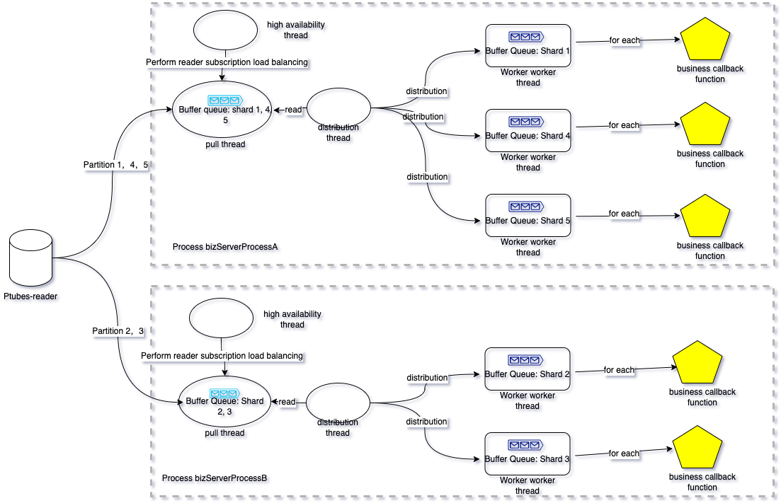
hint:
- Each "envelope" in the queue represents a batch of data; when calling back the user, it is also called back in batches, and the size of each batch can be adjusted [1,n) , when the batch size is 1, it is equivalent to a single serial callback in sequence.
- The same Ptubes-sdk task can run in multiple java processes. At the same time, multiple different Ptubes-sdk tasks can be run in the same Ptubes-sdk java process. Due to high availability and consistency considerations, you cannot start the same task twice in the same thread.
- The specific Ptubes-readers subscribed by the same Ptubes-sdk task may be different, depending on the "high availability thread" for dynamic reader IP selection.
- Fragmentation of Ptubes-sdk. It is a parallelization method born to improve data synchronization throughput. When starting a task, you can specify a shard field for each table, and Ptubes-sdk will follow a certain hash rule according to the value of the shard field (according to The fragmentation field takes the remainder of the hash), hashes the data of the same reader task into different sub-data streams, and each sub-data stream corresponds to a worker thread. Obviously, the use of sharding can improve the synchronization efficiency, and the data in the same sub-data stream is sent to the downstream sequentially. Data in different substreams are sent downstream in parallel, and there is no order correlation guarantee between them.
- Since the synchronization between the sub-data streams of Ptubes-sdk (data streams corresponding to each shard) is parallel, we save a "storage point" information for each shard. The "storage point" information of the shard saves the current shard's consumption of the data stream. As the data stream goes on, the "storage point" will gradually advance. In scenarios such as failure recovery and shard migration between processes, we can use the "storage point" to restore and restore consumption scenarios of different shards, and re-subscribe readers according to the specified "storage point" to ensure the consistency of the data stream.
- "Storage points" are asynchronously refreshed to persistent storage media. For details, please refer to the introduction of storage points in "2. Ptubes-sdk and Helix".
Ptubes-sdk relies on Helix for shard scheduling, so it also strongly depends on zk. Each Ptubes-sdk task corresponds to a "cluster" of helix, and we will create a default "Helix resource" named "default-resource" for each task, and each Ptubes-sdk shard corresponds to Helix "default- resource" a partition of the resource. Helix indirectly completes the load balancing scheduling of the Ptubes-sdk task fragmentation through the load balancing scheduling of the "default-resource" resource.
The specific concept of Helix can be introduced in Helix.
Just as Helix relies on zookeeper for shard scheduling, Ptubes-sdk also saves storage point information on zookeeper and uses the function of saving user-defined data provided by Helix https://helix.apache.org/1.0.2-docs/tutorial_propstore.html
For a Ptubes-sdk task taskA with 3 shards. The directory structure of its storage point on zookeeper is:
| Znode Path | tips | Znode Value Demo |
|---|---|---|
| /taskA/PROPERTYSTORE/partition-storage | is used to temporarily save the new number of shards and storage point information in scenarios such as moving in and out of shards, adjusting the number of shards, and modifying "storage points". | "{ "id":"partition-storage" ,"simpleFields":{ "partition-storage":"<br{"partitionNum":11,"buffaloCheckpoint" :{"uuid":"00000000-0000-0000-0000-000000000000","transactionId":-1,"eventIndex":-1,"serverId":-1,\ "binlogFile":-1,"binlogOffset":-1,"timestamp":-1,"versionTs":1622204269854,"checkpointMode":"LATEST"}}" } ,"listFields":{ } ,"mapFields":{ } }" |
| "/taskA/PROPERTYSTORE/0_taskA /taskA/PROPERTYSTORE/1_taskA /taskA/PROPERTYSTORE/2_taskA" |
Save the "storage point" of a shard | "{ "id":" -1" ,"simpleFields":{ "checkpoint":"{"uuid":"c055a63d-99c7-11ea-a39c-0a580a24b346","transactionId":54839254,\ "eventIndex":0,"serverId":36179070,"binlogFile":68,"binlogOffset":130958732,"timestamp":1624612320000,"versionTs":1622204269854,"checkpointMode ":"NORMAL"}" } ,"listFields":{ } ,"mapFields":{ }}" |
The structure of the storage point is
| Name | Type | Function | Example |
|---|---|---|---|
| uuid | string | uuid of transaction gtid | c055a63d-99c7-11ea-a39c-0a580a24b346 |
| transactionId | 64-bit integer | Transaction id of transaction gtid | 54839254 |
| eventIndex | 64-bit integer | Line number in transaction | 0 |
| serverId | 32-bit integer | Server ID | 36179070 |
| binlogFile | 32-bit integer | binlog file number | 68 |
| binlogOffset | 64-bit integer | binlog file offset | 130958732 |
| timestamp | 64-bit integer | Transaction timestamp | 1624612320000 |
| versionTs | 32-bit integer | Storage point version information | 1622204269854 |
| checkpointMode | String | "Enumeration Type: Storage Point Type EARLIEST LATEST NORMAL" |
NORMAL |
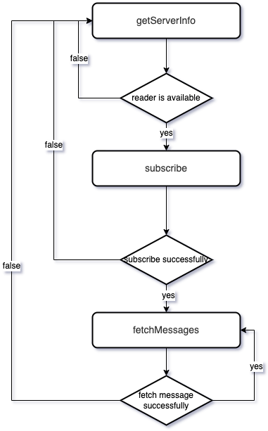
The entire data subscription and consumption process is completed between the sdk and the reader through three http interfaces.
| URI | Function | Remarks |
|---|---|---|
| /v1/getServerInfo | Get reader information | Get a reader information |
| /v1/subscribe | Subscribe | Subscribe to a readerTask, you need to call it after "Get reader information" |
| /v1/fetchMessages | Pull data | Pull a batch of data, it needs to be called after the "subscription" is successful |
The specific state transition is shown in the figure
Regarding the data consistency guarantee, the Ptubes system promises to guarantee the final consistency of the data. Regarding data consistency guarantee, we mainly guarantee through two aspects:
- Binlog parsing and storage phase guarantee The Writer service will persist the consumption of each shard of the Writer task (persistent every two minutes), so whether it is an instance restart or a shard transfer, it is guaranteed to re-subscribe the data and pull the data according to the current location of the shard. Cancellation fee.
- Binlog consumption stage guarantee (1) Regularly record the consumption location, and continue to consume from the last recorded consumption location after downtime/restart;
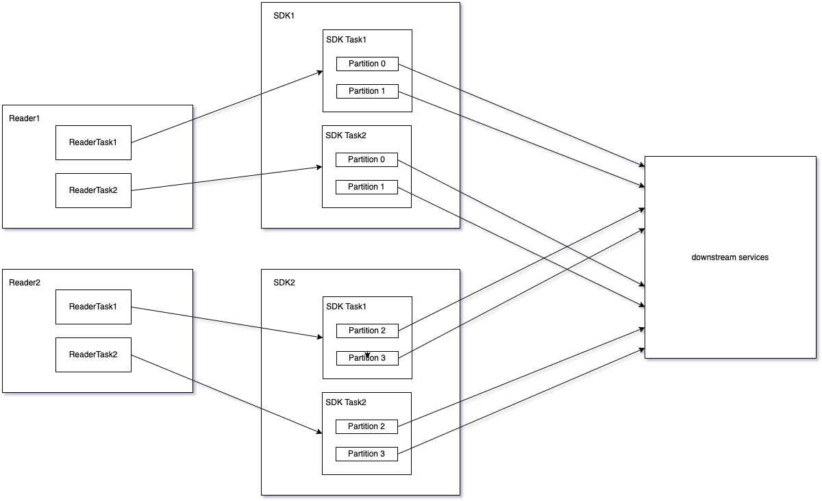
- Sharding latitude parallel: Allocate shards according to the sharding field hash, each shard is consumed independently, and the shards are consumed in parallel;
- Task latitude parallel: different tasks are consumed independently, and tasks are consumed in parallel;
- Machine latitude parallel: support horizontal expansion;
Order-related nouns in Ptubes are as follows:
- Number of shards: The number of concurrent writes of data downstream by Ptubes. Ptubes ensures that the data in the shards are sent in an orderly manner.
- Fragmentation field: Each table can specify a field in the table as the fragmentation field. After the value of the fragmentation field is processed by the internal hash algorithm of Ptubes, the number of the fragmentation can be calculated to obtain the fragmentation number for processing this piece of data.
Taking the MQ access method as an example, assuming that the shard field is id, the number of shards in Ptubes is 3, and the number of shards in Mafka is 5, the shard distribution of data with different ids in Ptubes and MQ is as follows:

The same row of data can be guaranteed to be hashed to the same shard for serial processing as long as the shard field value does not change, ensuring row-level order.
1.Selection of sharding fields
For the selection of sharding fields, there are the following suggestions:
- It is recommended to select the primary key or the unique key as the sharding field, which can ensure that the data is scattered into each shard as evenly as possible, and avoid the delay caused by hot spots caused by too much data processed by a certain one.
- It is recommended to select a field that will not change as the fragmentation field. The calculation of the fragmentation number is calculated based on the current value of this field. If the fragmentation field changes, it may lead to two changes of the same row of data. The slice numbers are not the same, which affects the order. 2.Modification of the fragmentation field After the service is connected, in principle, it is not allowed to modify the fragmentation field, except that the downstream service processing data is affected by the sequence problem.