© 2018 by Tony Fabris
https://github.com/tfabris/BlueGigaEmpeg
BlueGigaEmpeg is a project to use a Silicon Labs BlueGiga WT32i Bluetooth chip, combined with an Arduino Mega board, to act as an interface between an empeg Car Mk2/2a MP3 player and a modern Bluetooth-equipped car.


The empeg Car (small "e") player, also sold as the Rio Car, is an amazing in-dash MP3 player made from 1999-2001 whose features are still, nearly 20 years later, better than any other in-car MP3 solution available. However, the empeg Car didn't have Bluetooth since it wasn't in common use yet at the time.
Modern cars are becoming increasingly difficult to install aftermarket stereos into, due to the car touchscreen dashboards and the high level of integration of the stereo system into the other car systems. For owners of the empeg Car player, it's a problem, because it makes it hard to install our beloved player into our new cars. This project helps to solve this issue by adding digital Bluetooth output to the empeg Car player, allowing it to be connected to a modern car's factory stereo system, and integrate with its controls, in the same way that you would connect a smartphone to your car.
The BlueGigaEmpeg interface works in two ways:
-
Bluetooth A2DP connection allows high quality digital audio from the empeg Car player to play on the modern car's stereo speakers without needing an Aux Input on the car stereo. This is useful because many cars no longer have an Aux Input available, yet most new cars have Bluetooth.
-
Bluetooth AVRCP connection allows the empeg Car to receive commands such as "next", "previous", "pause", etc. from the Bluetooth connection, allowing the car stereo's touchscreen and steering wheel controls to be able to change tracks and control playback on the empeg. In addition, the same AVRCP channel allows track title and artist information to be displayed on the car stereo's touchscreen.
Demo video: https://www.youtube.com/watch?v=XS9U_ALc634
Some modification of the empeg Car is required in order for this to work. The Molex connector on the empeg docking sled's wiring harness, which is normally used for an external AM/FM tuner module, must be converted into a digital audio interface for sending audio data to the BlueGigaEmpeg module. Make sure to perform all modifications listed in the Installation section of this document.
-
This project only works with the empeg Car Mk2 or the Rio Car player. It will not work with the empeg Car Mk1 player.
-
At the time of this writing, I have tested this project on a very limited set of Bluetooth gear. So far, I have only tested it on:
- My Honda Accord 2017 factory stereo.
- Kenwood KDC-BT318U car stereo.
- Plantronics Voyager Edge Bluetooth headset.
- Onkyo TX-SR33 home stereo with Bluetooth input.
- Etekcity EA-TR1 standalone Bluetooth receiver.
- iHome Li-B33E7 toy Stardestroyer with a Bluetooth speaker.
-
Some Bluetooth stereo playback devices do not have full functionality. For example, The Onkyo listed above does not display AVRCP track titles, and my 2017 Honda does not have controls for Shuffle, Fast Forward, or Rewind. As far as I can tell, these are limitations of the devices themselves, not problems with the BlueGigaEmpeg: These same limitations exist when those devices are paired with smartphones, too.
-
This implementation uses the default codec for A2DP audio, SBC (Sub Band Codec). This introduces a slight delay in the audio, meaning that the music coming out of your car stereo speakers will be slightly delayed from the visuals on the empeg screen.
-
There are differences in Bluetooth implementation on various audio gear, and so there still might be bugs when using the BlueGigaEmpeg on your particular car stereo. This project is open source on GitHub, so that I can accept bug reports and code fixes from people with other brands of Bluetooth gear.
-
This is not intended to replace the empeg front panel user interface. This only allows you to do things like press Next Track, Pause, and Play on your car stereo. The full menu and user interface of the empeg is still needed for all other features of the empeg, such as selecting playlists. So this module won't let you mount the empeg in your trunk, unless you also have a display extender kit from Eutronix.com as well, which would allow you to reach the empeg front panel from the driver's seat. Unfortunately, Eutronix.com isn't selling display extenders any more. I was lucky to get a display extender several years ago when they were still being sold, so I'm able to mount my empeg in my trunk with this. But if you don't have a display extender kit, you will still have to mount your empeg someplace where you can reach it from the driver's seat.
- By the way, don't try rolling your own display extender by simply extending the wires. Special buffer circuitry is required in order to safely extend the empeg display, or you run the risk of damaging the empeg or its display.
Many thanks to the members of the empegBBS who helped with this so much. The initial chip suggestion was by BBS member Elperepat, and even though I ended up not using the particular chip that he suggested (I had trouble with that chip), it was his suggestion that started me experimenting with Bluetooth. Big thanks to Shonky who had many helpful suggestions and who pointed out the WT32i chip that is the one that finally got used in this particular design. Also particular thanks to Stuart Euans of Eutronix.com who created the empeg Display Extender board, which was critical to me being able to get my empeg mounted cleanly in my new Honda, since it doesn't have dash space for the whole empeg. Big thanks to Peter Betz of Betztechnik, who made a convenient and perfectly-sized breakout board containing the chip I wanted to work with, and who was very helpful and responsive in emails, and even made another manufacturing run with an updated design for me. And massive thanks to Mark Lord who assisted me in countless ways with the design and implementation, taught me a ton of important things, found my bugs, fixed issues with the Arduino compiler, modified his Hijack kernel to support this project, and pointed out all of my EE design flaws. And last but not least, thanks to the entire empeg team who made such a fantastic car MP3 player that we are still doing interesting things with it, nearly 20 years later.
Installing the BlueGigaEmpeg module requires some modifications to your empeg Car player. Make sure to go through each of the steps linked below.
- Prerequisites
- Modify empeg Car interior for I2S digital audio connection
- Disconnect all tuner modules from all sleds you own
- Empeg Car configuration changes
- Upgrade the empeg Car's Hijack kernel and set "Serial Port Assignment"
- Modify empeg's power connection to car
- Connect BlueGigaEmpeg to empeg Car player
- Mounting
Make sure you have all of these things before working with the BlueGigaEmpeg:
| Item | URL |
|---|---|
| Empeg Mk2 or Rio Car player | http://empegbbs.com/ubbthreads.php/forums/11/1/For_Sale |
| BlueGigaEmpeg Interface | [email protected] |
| Item | URL |
|---|---|
| Hijack Kernel for empeg | http://empeg-hijack.sourceforge.net |
| Tony's Empeg Logo Editor | http://empegbbs.com/ubbthreads.php/ubb/download/Number/7067/filename/logoedit17.zip |
| Arduino standalone IDE | https://www.arduino.cc/en/Main/Software |
| Latest BlueGigaEmpeg Arduino firmware | Direct download latest project file: https://github.com/tfabris/BlueGigaEmpeg/archive/master.zip |
| (Alternative) GitHub project for cloning, if you are using the Git tool: https://github.com/tfabris/BlueGigaEmpeg |
The BlueGigaEmpeg module works by connecting to the Molex connector on the empeg Car's docking sled wiring harness. This connector was originally intended for the empeg's external tuner module. The empeg must be modified so that the tuner module connector becomes a digital audio connection instead.
Do not connect the BlueGigaEmpeg to the tuner module connector until after completing the step in this document titled "Modify empeg Car interior for I2S digital audio connection". Also, once the I2S modification has been completed, connect the Molex tuner module connector only to the BlueGigaEmpeg, do not connect it to a tuner module, or to anything else. Damage may occur if these instructions are not followed.
Be sure you are capable of safely making internal modifications to the empeg Car player, and you are able to solder and shrink-tube electronic components. I take no responsibility for damage incurred while you are dismantling and modifying your empeg Car player.
To perform this step, you must be comfortable with disassembling the empeg Car player and removing the disk drive tray in such a way as to not cause damage to the player. In particular, there is risk to the components on the back side of the display board, and to the IDE header connector on the empeg motherboard. Use extreme caution when disassembling the empeg player.
You will be modifying the interior of your empeg Car so that there can be three wires coming out the docking connector which carry digital audio data ("I2S" aka "IIS") and can connect to the BlueGigaEmpeg unit. This is done by hijacking three of the wires originally used for the empeg tuner module on its Molex connector. This tuner module connector will instead plug into the BlueGigaEmpeg electronic assembly, which contains the Bluetooth chip and the Arduino.
The empeg tuner module will no longer work after this modification, and damage may occur if you connect one to your player. If you have a tuner module, now is a good time to disconnect it from the sled and put it away.
Partially disassemble your empeg player by carefully removing the fascia, lid and drive tray, as described below. You must do the disassembly gently, so as not to damage the empeg. Make sure not to break any of the components sticking off the back of the display board as you do this.
-
Use a 2.5mm hex tool to carefully remove four hex bolts from the fascia.
-
Gently remove fascia, buttons, rotary control, and colored lens.
-
Extend the hinged pullout handle during the next step. This lowers the keeper hooks on the top of the player, which keep it hooked into the sled and which will also interfere with the lid removal if they aren't lowered. If you have trouble removing the lid in the next step, first double check that the handle is in the extended position.
-
Remove lid by sliding it forward and upward over the tabs. This may be tricky on some players, requiring some gentle levering against the tabs with a screwdriver. You shouldn't need to bend or force anything, but it may be a bit of a tight fit as you remove it. Use caution not to slip and damage the components on the display board. As shown in this photo:

-
Do not remove the display board.
-
Remove four Pozidriv screws on the outside sides of the player which are holding the disk drive tray in place. Be careful not to strip the screw heads by using the wrong size or type of screwdriver. Make sure to select a screwdriver which fits the heads of the screws good and tight. Information about Pozidriv screws can be found here: https://en.wikipedia.org/wiki/List_of_screw_drives#Pozidriv
-
Gently lift out the drive tray. Make sure not to bump any of the components on the back of the display board. There are some particularly fragile components there, and it's really important that you don't bump them, or your empeg display will stop working entirely. They are really easy to hit, too, so be super careful.
-
When lifting out the drive tray, take note of how the IDE cable is folded and routed so that you can put it back exactly as you found it.
-
Do not disconnect the IDE cable. You should be able to set the drive tray gently aside, without disconnecting the cable, and also without putting any stress on the cable.

Refer to the annotated photograph "I2S Wiring Modification Photo.jpg" to help understand the wiring instructions below.
I2S Wiring Modification Photo.jpg:

Locate 5 blank I2S pads on the front left side of the empeg motherboard. Pads are outlined in a white silkscreen rectangle with the letters "IIS" next to the outline. White silkscreen rectangle will have one corner of it with a small diagonal "snip" to the corner which will indicate pad number 1 of the set of 5 pads. This diagonal snip will be towards the back of the empeg, and the remaining pads continue towards the front of the empeg. Pads are not individually labeled with numbers, but understand that they are logically numbered 1 2 3 4 5 starting from the back and going towards the front of the empeg. The pinouts of these five pads are:
  1 = IISC  aka  SCK     aka "serial clock"
  2 = IISW  aka  WS      aka "word select"
  3 = GND   aka  Ground  same as chassis ground of empeg
  4 = IISD1 aka  SD      aka "serial data" (1 of 2)
  5 = IISD2 aka  SD      aka "serial data" (2 of 2)
Carefully solder the three supplied jumper wires to pads 1,2, and 4, and you must keep track of which wires are soldered to which pads.
Note: The coloring of the supplied jumper wires is random and arbitrary. They are each colored differently, so that you can tell which ones were soldered to which I2S pads, but their particular colors are not intended to match anything.
When soldering, make sure the jumper wires and the solder joints are flat to the board instead of sticking upwards. The disk drive tray gets close to that location when mounted, so make sure they don't have a chance to contact the tray.
After soldering, cover the solder points with tape or some other insulator to prevent them from shorting out on the drive tray.
Locate the two white connectors on the back part of the empeg motherboard which connect two groups of small colored wires to the docking connector assembly. Locate the rightmost of the two connectors nearest the Ethernet port on the back of the empeg. Unplug this connector, and using a tiny flat tool such as the tip of a jeweler's screwdriver, lift up the small white tabs and gently disengage and pull out the pins. Pull out only the rightmost three pins nearest the Ethernet connector to free up those three wires. These wires are colored, going from left to right, yellow+green, red, and brown. The brown wire is the one on the right end closest to the Ethernet connector, the red wire is the second from the end, and the yellow+green wire is the third from the end.
With the three wires disconnected from the white connector, plug the white connector back into place with the remainder of its wires still connected. You should now have three wires inside the empeg, each with one end still connected to the docking connector assembly, and their other ends loose with small pin connectors on the ends of them.
Carefully solder and shrink-tube your three jumper wires directly to these pin connectors in the exact order described below. Shrink tubing has been supplied with the BlueGigaEmpeg. Don't forget to put the shrink tubing onto the jumper wires before you solder them.
Solder your jumper wires to the empeg interior wires in this order:
- IIS Pad 1 (IISC): jumpered to the yellow+Green wire which was originally the third wire the from end of the white connector.
- IIS Pad 2 (IISW): jumpered to the brown wire which was originally the end wire on the white connector.
- IIS Pad 4 (IISD1): jumpered to the red wire which was originally the second wire from the end of the white connector.
After you have done this, your empeg's I2S pads will, when docked, now be carried out the back of the empeg, via the docking sled, into the Molex tuner module connector.
Make sure that your jumper wires are carefully tucked down around the left side of the empeg and out of the way of the disk drive tray assembly as shown in the photo linked above.
Glue down your jumper wires near the I2S pads so that they do not wiggle and rip away the I2S pads. Some empeg Car units will have a chip at that location that you can glue onto, others will have a blank area of the PCB in that location that you can glue onto. Use RTV silicone or cyanoacrylate superglue to glue them down. Use a small amount of glue, and make sure the blob of glue does not "stick up", since the disk drive tray gets very close to that location.
After the glue is fully dry, carefully reassemble the player. Reassemble in the reverse order of disassembly. Make sure to put everything back where you found it, in particular, make sure the IDE cable is folded and routed the same way as it was when you disassembled the player.
When reassembling, be careful not to overtighten the hex bolts which hold the fascia in place, they should only be finger-tight. If you overtighten them, you may crack the fascia and/or prevent the buttons from working correctly.
Final wiring positions and colors:
| Empeg IIS pads | Int. empeg wires * | Int. white conn pos ** | Sled Tuner Plug | BlueGigaEmpeg Tuner Plug | Bluetooth Chip | Usage |
|---|---|---|---|---|---|---|
| 1 IISC | Yellow+Green wire | Third from end | 7 Purple | 7 SCK | 30 PCM_CLK | Serial Clock |
| 2 IISW | Brown wire | Right end | 2 Grey | 2 WS | 29 PCM_SYNC | Word Select aka Sync |
| 4 IISD1 | Red wire | Second from end | 1 Pink | 1 SDIN | 27 PCM_IN | Serial Data aka PCM Audio Data |
| 4 Black | 4 GND | GND | Universal Ground | |||
| 8 Blue | 8 12vPower | Power to voltage regulator |
*  (These are the interior wires running between the docking sled and the
    white connector on the empeg motherboard.)

** (Original positions of these wires on the white connector near the
    Ethernet plug, now disconnected from that connector.)
After completing the I2S wiring modification, the external empeg tuner module will no longer work. Also, damage may occur if you connect a tuner module to a modified empeg.
To prevent problems, make sure to disconnect any tuner modules from any docking sleds that you own, and pack them away somewhere safe. After making the I2S wiring modification to the empeg, do not use a tuner module any more.
Label your empeg with the supplied stickers, which tell your future selves not to use this particular empeg with tuner modules any more.
The following configuration changes are required for BlueGigaEmpeg to work correctly.
I have tested the BlueGigaEmpeg with version 2.00 of the empeg Car software. It is designed to work with version 2.00 Beta 13 or version 2.00 Final. I have not tested it with the 3.0 Alpha version of the empeg Car software, but theoretically it should work.
Using the Emplode or Jemplode software, edit the empeg Car's config.ini as follows.
If you are using Emplode on Windows, you must first edit the Microsoft Windows registry before it will allow you to alter the config.ini. First, run REGEDIT.EXE in Windows and modify the following key:
 HKEY_CURRENT_USER
   Software
     SONICblue
       emplode
         2.0
           Settings
              (Inside the "Settings" key, create a new DWORD value named:)
                allow_edit_config
                  (with a value of)
                    1
Then restart the Emplode software. Emplode will now have a menu option which allows you to edit the config.ini on the player.
Change the settings in config,ini as follows (adding new section headers such as [hijack] only if that section does not already exist):
[hijack]
suppress_notify=2

[output]
notify=1

[serial]
car_rate=115200
These settings are case-sensitive. Make sure to synchronize with the player after changing the config.ini settings.
The latest version of Hijack is required in order for BlueGigaEmpeg to work correctly. Install the latest Hijack Kernel onto the empeg Car player if it is not already installed. Link to the Hijack kernel is found in the Prerequisites section of this document. Make sure it is Hijack version 524 or later.
In order to install the latest Hijack Kernel onto the empeg, you must connect the empeg directly to your computer's RS-232 serial port, or to a USB-to- RS-232 adapter cable if your computer does not have an RS-232 serial port. Make sure the serial port drivers are installed and that you can see the empeg bootup messages correctly through a serial terminal program.
To install the Hijack kernel, run Tony's Empeg Logo Editor. Link to the Logo Editor program is found in the Prerequisites section of this document. This program is a Windows program, but it should also work correctly on a virtualized version of Windows. For example, I have used it successfully running under Parallels on a Mac. On the File menu of the logo editor program, select "Kernel Flash Utility" and follow the instructions.
Once Hijack is installed, open up the Hijack kernel settings on the player via a long-press on the player's rotary encoder dial. Change "Serial port assignment" to "Player uses serial port" and follow the on-screen instructions to reboot the player.
I recommend that for this installation, you connect the empeg's wiring harness to your car differently than if it were a standard car installation. It might not be required for your installation, but it was required for mine, so doing this now could save you time and hassle later.
This BlueGigaEmpeg is designed to turn the empeg into a secondary Bluetooth input into a modern car stereo, rather than being the car's main stereo system. In this situation, the empeg's sleep mode, the empeg's "memory" power connection, the way the BlueGigaEmpeg module gets its power from the empeg tuner connector, and the way the car stereo issues Bluetooth commands when you shut off the ignition, all combine to cause some interesting problems with power state transitions.
I found that if I connected the empeg to my car's power via the regular method (i.e., car accessory power to the orange ignition wire on the sled, and car constant 12v power to the yellow memory wire on the sled), then there were certain unusual states that it could get into. Sometimes I would shut off my car, but the empeg would come back up out of sleep mode and play tracks silently to an unconnected Bluetooth module, draining my car's battery.
To prevent this problem from happening to you, I recommend connecting power between the car and the empeg like this instead:
-
Orange "ignition" wire from empeg: Connect to car 12v accessory power.
- "Acessory Power" is the power that is only on when your car ignition is on, or your key is set to the "accessory" position so that your car stereo is turned on. Or the pushbutton equivalent of that, if your car doesn't have a physical key.
-
Yellow "memory" wire from empeg: Also connect to car 12v accessory power (instead of the usual constant power).
-
Do not connect your car's constant 12v power to any part of the empeg.
-
White "lights on" wire from empeg: Connect to car dash illumination power.
-
Black "ground" wire from empeg: Connect to car ground.
-
Tuner module and serial plug connectors: Connect to BlueGigaEmpeg module.
That should be all you need. No analog audio or amplifier connections, because the Bluetooth takes care of that now. No cellphone mute wire, because the Bluetooth takes care of that now. No amp remote wire, because there is no amp connected directly to the empeg.
When connected this way, the empeg does not receive a 12v constant power source. Instead, it will completely lose all power when you turn off the ignition, rather than going into sleep mode. The empeg and its attached BlueGigaEmpeg module will always power on and off at the same time as the car stereo, and nothing will get confused about power state. You might lose the date/time information on the empeg sometimes, but your modern car likely has a perfectly functional clock of its own. The empeg is already designed to save its playback position when it unexpectedly loses power, so it will continue to work correctly in this wiring scheme.
In a normal car install, with analog audio and an amplifier connected to the empeg, the wiring scheme described above would cause a pop sound when turning off the ignition. But with the BlueGigaEmpeg, all audio is digital, and goes through the Bluetooth connection, so there will not be a pop sound.
By the way, I'm using a set of "Add-a-circuit" fuse adapters to connect my empeg to the car's power at the car's fuse panel. This let me avoid the hassle of trying to tap into the factory stereo wiring. If you use this method, make sure to research to find the correct size for your car. For example, mine are the "low profile mini fuse" type. Some helpful links:
- https://en.wikipedia.org/wiki/Fuse_(automotive)
- https://www.google.com/search?q=Add-a-circuit+Fuse+Adapter
Only do this step after completing the prior step in this document titled "Modify empeg Car interior for I2S digital audio connection".
If the I2S wiring modification has been completed, connect the tuner module connector from the empeg Car player docking sled to the tuner connector on the BlueGigaEmpeg module. This plug carries 12v power to the BlueGigaEmpeg module and also carries I2S audio data.
Connect the RS-232 serial plug from the empeg Car player docking sled directly to the serial port on the BlueGigaEmpeg module. This plug carries the play/pause/next control commands from the BlueGigaEmpeg to the empeg Car player software, and also carries the track metadata (title/artist/etc) from the empeg Car player software to the BlueGigaEmpeg module.
The USB "type B" connector on the outside of the BlueGigaEmpeg module enclosure is left disconnected during normal operation. It is only used for debugging, and for uploading the latest Arduino sketch to the BlueGigaEmpeg module. However, if you are mounting your BlueGigaEmpeg module permanently in a hard-to-reach location in your car, make sure to run a USB cable from this port to a reachable location, so that you can connect a laptop to it later. See the section of this document titled "Debug Bluetooth Connection if needed" for more details on how to use the USB connector for debugging.
The BlueGigaEmpeg module can be permanently mounted to the car if needed. Four mounting tabs are included on the casing for this purpose, though Velcro or other methods can work too. It can also be simply stuffed in somewhere with the rest of the attachment wiring, as long as it's not "dangling" and putting stress on the attachment cables.
When mounting:
-
Try to leave the BlueGigaEmpeg's recessed RESET/PAIR button reachable somehow. You won't need to use it very often, but when you do, it's super nice to be able to reach it. If you can't make the button reachable, then the USB cable will also allow you to pair, but the button is much more convenient.
-
Make sure to leave the BlueGigaEmpeg's USB debug port accessible for firmware updates and debugging. If you have mounted the BlueGigaEmpeg in a hard-to-reach location, then my best recommendation is to find a long USB type-A-to-type-B cable (It's a standard USB printer cable, you probably have a few extras of these lying around already), attach it to the BlueGigaEmpeg's USB debug port, and route it somewhere in your car that can be reached with a laptop.
-
Make sure the empeg itself is mounted so that its front panel is still visible and accessible from the driver's seat. The BlueGigaEmpeg isn't a replacement for the empeg's user interface.
Turn on your car's ignition to apply power to the empeg. This should also apply power to the connected BlueGigaEmpeg module via the tuner module connector. Make sure the empeg is not in "sleep" mode, since power to the tuner module connector is turned off in sleep mode.
The first time you use the BlueGigaEmpeg, you will need to pair it with your Bluetooth car stereo. The BlueGigaEmpeg has a recessed RESET/PAIR button for this purpose.
-
Turn the volume level on your car stereo down to a low level, so that you're not blasted when the pairing process is complete.
-
If your car stereo has a feature that lists existing Bluetooth pairings, and if there is an existing entry for "empeg Car" from an earlier pairing (for example, if you need to pair a second time), make sure to delete that earlier entry from the car stereo, because its security key will become invalid when you press the RESET/PAIR button in the next step.
-
Press the recessed RESET/PAIR button on the BlueGigaEmpeg module. You do not need to hold down the button, a single click is all it needs. The adjacent LED should light up blue for about 60 seconds or so.
- If you can't reach the RESET/PAIR button, then it is also possible to initiate pairing from the USB debug connection, via a connected laptop, by typing a Z followed by pressing the Enter key in the Arduino Serial Monitor. See "Debug Bluetooth connection if needed" for more information.
-
On the car stereo, initiate its pairing mode while the blue LED on the BlueGigaEmpeg module is lit. If the stereo offers you a list of devices to pair with, then look for the device "empeg Car" and pair it.
- Some car stereos will allow you to pair without needing to press the recessed RESET/PAIR button on the BlueGigaEmpeg. For stereos with this capability, you will be able to see and select the "empeg Car" from the list of nearby devices, even when the blue LED on the BlueGigaEmpeg is not lit. If this is the case, it is still OK to press the button, the pairing should succeed whether you press the button or not.
-
Your car stereo might put up a random number on the screen and prompt you to confirm that number on the device. If it does, the BlueGigaEmpeg will automatically confirm that number for you.
-
Your car stereo might prompt you to press a button to confirm or finalize the pairing process, or it might prompt you to choose the connection type. For instance, on my Honda, its touchscreen will prompt me to choose whether to pair it as a music device, a phone device, or both. If you get a prompt like this, choose the music device option.
-
If the pairing still doesn't work, try sleeping the empeg (long press on top button), then waking it up again with another button press. This will reboot the BlueGigaEmpeg module.
-
If pairing still doesn't work, try turning off the car stereo completely (turn off car ignition), turn on the car ignition again, sleep and wake the empeg, and try again from the top. This ensures that both devices have been fully rebooted.
-
When the pairing is completed, set the volume. With the car stereo volume still turned down to a low level, turn the volume on the empeg Car front panel all the way up to 0.0 db. Then gently increase the volume on the car stereo to the desired listening level. From now on, control the the overall volume level from the car stereo controls and leave the empeg set to 0.0 db. Note that there are features in the Hijack kernel for setting the volume level on startup, so if the empeg keeps booting into a low volume mode, check the Hijack kernel settings for "Volume Level on Boot" and set it to "Previous".
Car and empeg should be playing nicely together now, assuming everything else is working correctly. Audio from the empeg comes out of your car stereo's speakers, the car stereo's track change controls will change tracks on the empeg, and the track titles will appear on the car stereo's screen.
See Troubleshooting if you encounter any problems.
After you have successfully paired with your car stereo once, you should not need to pair it again each time you get in the car. It should automatically reconnect each time you start your car.
Some car stereos will let you pair your phone and the empeg at the same time. Not all car stereos will have this feature. My Honda allows me to do this, and it works like this: When pairing, the car's touch screen lets me choose whether the paired device is a phone device, a music device, or both. I choose to pair my phone as a phone, and the empeg Car as a music device. Then, each time I start my car, they both pair up correctly. I can use the steering wheel controls to initiate a speakerphone call, which automatically pauses playback on the empeg, and resumes playback after I hang up the call.
The empeg Car should automatically pause its playback when you turn off the car stereo. It should also pause when you switch to another input source on your car stereo, such as switching to the radio or to the CD player. It should automatically resume playback when you turn the stereo on, or switch back to the Bluetooth input.
The empeg Car should automatically pause its playback immediately after its boot sequence is complete, then it will wait until there is a successful Bluetooth connection, then it will resume playback after Bluetooth is connected. If Bluetooth is already connected by the time that the empeg boot sequence is complete, it will resume playback when it is done booting up. This prevents the empeg from playing music silently while it waits for your car stereo to boot up. This is needed for some cars whose stereos have long boot times which exceed the empeg boot time. My Honda has a stereo like that, it takes about 25 seconds to boot up and be able to play Bluetooth music, more than twice as long as the empeg takes to boot up. Without this feature, there would be about 15 seconds' worth of song "lost" (played silently) each time I started my car.
The BlueGigaEmpeg implements a specific set of Bluetooth controls. Not all car stereos support all of these controls. For instance, my Honda does not do Fast Forward or Rewind with any Bluetooth device, so those particular features don't work on my Honda.
- Pause
- Play
- Previous Track
- Next Track
- Rewind
- Fast Forward
- Stop
- Pressing Stop on the car stereo should pause the empeg.
- Shuffle
- Shuffle is implemented as a toggle on/off command. If your stereo has a feature to display the current shuffling state (displaying whether shuffle is currently turned on or turned off), it will not be correctly indicated on your stereo's screen. The empeg car does not report its shuffle state to the serial port, so the BlueGigaEmpeg cannot report the correct state of shuffle to the car stereo. Pressing the shuffle button on the car stereo should still toggle the empeg's shuffle on and off, regardless of the indicated state. Since the empeg has different types of shuffle, toggling shuffle from the car stereo will send the "%" command to the serial port on the empeg, which I believe will toggle back and forth between "shuffle off" and "shuffle using the last shuffle type that you previously selected".
The items below are not implemented on the BlueGigaEmpeg, but you can still do them on the empeg's front panel.
- Music search or playlist/track browsing
- Menu selection and navigation
- Repeat mode (repeat all tracks, repeat one track, etc.)
- Volume up/down/mute (set empeg to 0.0db and use car stereo volume instead)
The empeg tuner connector only supplies power to the BlueGigaEmpeg module if the empeg is awake. If you put the empeg into sleep mode via a long press on the top button, it will go to sleep, but that also means the Arduino+Bluetooth assembly stops receiving power. This is actually good: you want to be able to turn the Bluetooth on and off and reboot it sometimes, and it's easy to do that just by sleeping and waking the empeg from its front panel.
Most of the time, leave the player in "awake" mode. When you shut off the car ignition, the player fully shuts down. When you start the car again, the empeg starts up in "awake" mode and immediately supplies power to the BlueGigaEmpeg module, which then automatically connects to the car stereo head unit.
- Reboot the Bluetooth module
- Always use the latest firmware
- Pairing issues
- Other issues
- Set Bluetooth PIN code if needed (most likely not needed)
- Test AVRCP behavior and set serial port crossover jumpers if needed
- Debug Bluetooth connection if needed
Some problems can be solved by rebooting the Bluetooth module. Simply sleep the empeg by pressing and holding the top button, then wake it up again with another button press. This bounces power to the tuner module connector where the BlueGigaEmpeg gets its power.
When troubleshooting, always start with the most recent versions of the BlueGigaEmpeg firmware and Hijack Kernel.
-
To update the BlueGigaEmpeg firmware, see the section titled "Updating firmware".
-
To update the Hijack kernel, see the section titled "Upgrade the empeg Car's Hijack kernel and set Serial Port Assignment".
When you press the recessed RESET/PAIR button on the BlueGigaEmpeg, it does the following:
-
Erases all previous Bluetooth pairings and security keys from the Bluetooth chip.
-
Resets the Bluetooth chip to default settings.
-
Looks for Bluetooth devices to pair with for about 60 seconds, and pairs automatically with the first one that it sees. Starting with version 1.1.5 of the BlueGigaEmpeg sketch, it will alternate between searching for devices and listening for devices during pairing mode.
-
The blue RESET/PAIR LED is lit during this pairing mode, and will turn off once pairing is complete, or once the 60 seconds has run out.
Paired devices share a set of security keys with each other. Pressing the recessed RESET/PAIR button on the BlueGigaEmpeg module erases previous pairings, thus erasing those keys from the WT32i chip. This is important if your car stereo remembers an onscreen list of existing paired Bluetooth devices and gives you the option to manage those devices: The empeg Car's entry in that list becomes invalid when you press its RESET/PAIR button. So you will need to delete the empeg Car from that list before trying to pair it a second time. Conversely, if you delete the empeg Car from your car stereo's list of paired devices, you'll also need to clear the security key from the Bluetooth chip by pressing the RESET/PAIR button on the BlueGigaEmpeg module.
Sometimes Bluetooth devices can get into odd states which require a reboot to fix. If you're having pairing troubles, try rebooting the BlueGigaEmpeg by sleeping and waking the empeg with a long press on the top button of the front panel, followed by another button press to wake it. If that doesn't work, try rebooting both devices: Reboot the car stereo by turning the ignition off and on again, and also reboot the BlueGigaEmpeg by sleeping and waking the empeg.
When trying to pair, turn off any nearby Bluetooth devices which are in "discoverable" mode or "pairing" mode. The BlueGigaEmpeg has no user interface, so it has no way to pick and choose which device it's trying to pair with. It will attempt to pair with the first one it sees, so if there's more than one pairable device in the immediate vicinity, it might not get the one you think it's getting.
If necessary, experiment with different positioning of the BlueGigaEmpeg module in relation to your car stereo. The Bluetooth chip is located near the top center of the unit, near the recessed RESET/PAIR button. It will work best if it has line of sight to your car stereo and/or is physically close to it.
If there is good audio, but commands such as next/previous track and play/pause don't work, and if track titles do not display on your car stereo, See the section titled "Test AVRCP behavior and set serial port crossover jumpers if needed".
Check to make sure that the wires for the serial port connection (or any other connection for that matter) have not pulled out of the back of the docking connector on the empeg sled. This is a common problem. See here for the correct wiring scheme: http://empegbbs.com/ubbthreads.php/topics/370309/
If AVRCP commands and track titles fail to work intermittently, and it has occurred after you have uploaded a new version of the BlueGigaEmpeg firmware to the Arduino, then check to make sure that your Arduino IDE's compiler files have the corrected values for the serial port buffers as described in the Updating firmware section.
If you have trouble with the empeg waking up after you shut off the car ignition, see the section here: "Modify empeg's power connection to car".
If you notice that there is a slight delay between the visuals on the empeg screen compared to the sound coming out of the car stereo speakers, this is normal. The Bluetooth chip uses the Sub Band Codec (SBC) which is the default codec for A2DP audio, and that codec has a slight latency.
Check to see if the issue you're encountering is a known bug or a previously-closed bug:
-
Open bugs: https://github.com/tfabris/BlueGigaEmpeg/issues
-
Closed bugs: https://github.com/tfabris/BlueGigaEmpeg/issues?q=is:issue+is:closed
If you have other problems not listed here, see this section: "Debug Bluetooth connection if needed".
BlueGigaEmpeg does not usually require a PIN code to successfully pair. Before trying to modify the PIN code, simply try pairing first.
Some stereos will prompt with a random set of digits on the screen and ask you to confirm those digits on the Bluetooth device with a Yes/No prompt. This is not the same thing as a PIN code. In those cases, the BlueGigaEmpeg will try to automatically answer this prompt with a "yes" answer so that no user interaction will be needed.
In rare cases where a special PIN code is is needed, there is a place in the "BlueGigaEmpeg.ino" source code file where you can modify the PIN to something other than "0000". Find the line in the sketch that defines the variable "btPinCodeString". That line contains the "0000" default PIN code. Change it to your correct PIN code for your stereo and re-upload the sketch to the Arduino. It can accept PIN codes up to 16 digits long.
If you are lucky, the empeg will respond to commands from your car stereo's controls for play, pause, next track, etc., and the car stereo will display track titles on its touchscreen. This is done via the Bluetooth Audio Video Remote Control Profile ("AVRCP"), and the serial port connection to the empeg Car.
However, if the Bluetooth pairs successfully and streams music, but you are unable to play/pause/next the empeg via the car stereo's controls, and the track titles don't show up on the car stereo's screen, then try the following.
-
First check to make sure that your car stereo even has the features you're trying to use. For example, try pairing your smartphone to the car stereo and see if you get play/pause/next/previous commands, and track titles, with that.
-
If AVRCP commands work with your smartphone, but not with the empeg, double check that the serial port is actually working on the empeg docking sled, and that none of its wires have pulled out of the docking connector.
-
Verify that you get good serial port messages from the empeg when you connect the RS-232 serial cable directly from your computer to the empeg docking sled serial port connection (with the BlueGigaEmpeg out of the picture), and verify that they are coming in correctly at 115200 BPS.
-
If the serial port is good, but you still get no joy with AVRCP commands or track titles, then make sure that you correctly upgraded your player to the latest Hijack kernel as described here, and that you performed the changes listed in "Empeg Car configuration changes".
-
If the above things are verified as good, then use debug mode, temporarily enable the "displayEmpegSerial" feature in the Arduino sketch, upload the sketch to the Arduino, cycle the power on the empeg, and watch to make sure that serial output from the empeg appears on the screen. If no serial port messages from the empeg appear in the debug console with "displayEmpegSerial" enabled, then there is a chance that the serial wiring is crossed over. Try changing the crossover jumper block inside the BlueGigaEmpeg module:
-
The crossover jumpers exist because I have seen empeg sleds with different wiring on the RS-232 plug. Some are wired straight, some are wired crossover. I added the jumpers so that you can set the BlueGigaEmpeg board as straight or crossover to compensate for this. The BlueGigaEmpeg ships with its jumpers in the crossover configuration by default, in order to compensate for the situation where the empeg sled serial plug is wired as straight through. I think/hope this is the most common configuration.
-
To change the jumpers, open the BlueGigaEmpeg enclosure with a 2.5mm hex tool and lift out the electronic board assembly. Look near the button and LED, and you'll see the RS-232 Crossover jumper block, with silkscreened instructions on the board to describe how to change the setting. Set the RS-232 Crossover jumper block to the opposite setting.
-
Place the board assembly back into the BlueGigaEmpeg enclosure so that the recessed RESET/PAIR button and the LED fit into their corresponding holes on the enclosure. If the LED got bent, straighten it carefully so the LED fits into its hole in the casing.
-
You should not need to force the BlueGigaEmpeg board assembly back into its casing, but it is a very precise fit so that it doesn't rattle. You might have to nudge and coax it a bit into its final position, but it should fit perfectly without forcing it. When placing the lid back onto the enclosure, the lid should fit gently and perfectly, and should close completely, without forcing it down. If you feel like you need to force the lid closed, then you either have the lid backwards, or you haven't gotten the board assembly seated back into the casing correctly, so try again.
-
When reassembling the BlueGigaEmpeg enclosure, make sure to put the screws back in carefully. If you're using a powered screwdriver, use a slow speed, so that friction and heat don't melt the 3D printed plastic, thus stripping the screw holes. Make sure not to overtighten the screws, which would also strip the screw holes. Just make them tight enough to keep the casing cleanly shut.
-
Recheck and see if this fixed the issue, then return the variable "displayEmpegSerial" back to its original state, and re-upload the sketch to the Arduino.
-
-
If changing the crossover jumpers does not make the empeg's serial port messages appear on the Arduino debug console with "displayEmpegSerial" enabled, then you've still got a serial port problem. Put the crossover jumpers back to their original setting, and re-diagnose from the top.
Everything hopefully will work perfectly, but there may be bugs in the Arduino code because this was not tested with a wide range of Bluetooth gear. If you need to debug the connection, here are some helpful tips.
The BlueGigaEmpeg module is an Arduino command+control board, sandwiched to a custom interface board, connected to a BlueGiga WT32i Bluetooth chip. The firmware running on the Arduino allows for a terminal debug interface to the Bluetooth chip. This is automatically invoked when you connect a USB cable from your computer to the Arduino's USB connector, which is the USB-B connector accessible on the outside of the BlueGigaEmpeg casing. Once connected, a USB-serial port will appear as a device on your computer through the UART chip built into the Arduino.
Installing device drivers for the Arduino's USB-serial UART will be needed. To install the device drivers and get the Arduino Serial Monitor working, install the Arduino IDE by following the instructions in the section "Updating firmware". This will also ensure that you are updated to the latest BlueGigaEmpeg firmware before trying to debug any problems.
Once the device drivers are working for the Arduino's USB-serial UART, then the "Serial Monitor" feature built into the Arduino IDE program will work as the debug console. To run it, do the following:
-
Make sure the empeg is powered off or is in sleep mode.
-
Connect the USB cable between the computer and the Arduino port (the USB "type B" connection which is accessible on the outside of the BlueGigaEmpeg casing).
-
Launch the Arduino IDE that you installed as part of "Updating firmware".
-
Select the "Tools" menu, select "Board" and select "Arduino/Genuino Mega or Mega 2560".
-
Select the "Tools" menu, select "Processor" and select "ATmega2560 (mega2560)".
-
Select the "Tools" menu, select "Port" and select the correct serial port that represents the connected Arduino (this will be different on each system and each USB port on the computer).
- If the correct serial port for the Arduino is not in the list, check to make sure you have connected the cables in the correct order in relation to powering on the devices. See the note about startup order here.
-
Select "Tools" then "Serial Monitor", or press the magnifying glass icon in the upper right corner of the window. The serial monitor will appear. Set it to 115200 BPS and set line endings to "both NL & CR".
-
Keep in mind that the BlueGigaEmpeg interface module will reboot (the Arduino code will restart) each time you open the serial monitor, and the WT32i Bluetooth module will be automatically rebooted at that time.
-
Apply power to the empeg. You should see the message "empeg player boot process has started" appear in the Serial Monitor.
-
If you disconnect and reconnect the USB cable from the Arduino, you will need to close and reopen the Serial Monitor again. If you connect to a different USB port on the computer, you will also need to select a different port from the "Tools" menu in the Arduino IDE. Also keep in mind the required startup order, as described here.
When connected to this serial terminal interface, everything you type is sent to the Bluetooth chip as a command, and all of the chip's responses are shown on your screen. You will also see all commands that the Arduino sends to the Bluetooth chip automatically, and see all of the chip's responses to them.
You may also type certain specific commands to the serial port to control the empeg. Type a single character followed by pressing the Enter key. The following commands are supported:
- "N" - Next track.
- "P" - Previous track.
- "C" - Play (think "continue").
- "W" - Pause (think "wait").
- "F" - Begin fast forwarding.
- "B" - Begin rewinding (think "backwards").
- "A" - Stop fast forwarding or rewinding (think "abort").
- "%" - Toggle Shuffle on or off.
- "+" - Increase the volume of the empeg by one notch.
- "-" - Decrease the volume of the empeg by one notch.
- "Z" - Place the BlueGigaEmpeg module into pairing mode for approx. 60 seconds.
The BlueGigaEmpeg module can connect to any of these power sources:
-
It can obtain power from the tuner module connector on the empeg's docking sled wiring harness. This is the default way for it to get its power during normal operation.
-
It can obtain power from the USB plug, the Arduino USB "type B" port accessible on the BlueGigaEmpeg casing. This allows you to upload new Arduino firmware to the BlueGigaEmpeg module while it is disconnected from the empeg's docking sled.
-
Both of the above can be connected at the same time during a debugging session, and the BlueGigaEmpeg will get its power from either one.
Because both power sources can be connected at the same time during debugging, if you are using the USB cable for debugging mode, the sequence order of connecting the cables and applying power is important.
If you connect the BlueGigaEmpeg to the empeg docking sled and power it up, and then attach the Arduino USB cable to the computer afterward, then the Arduino USB port communications with the PC are not initialized (power from the tuner connector came first) and so the USB connection will not identify itself to the computer. This causes a problem: The computer cannot find the Arduino's USB UART and is unable to connect to the debug port.
So, to successfully debug via the Arduino USB debug cable, you must connect the USB cable to your computer first, with the computer on, before applying power to the empeg (or before waking the empeg from sleep). Meaning, if you are debugging in the car, you should connect the USB cable first, and then turn on the ignition. If you are debugging indoors, connect the USB cable first, then connect the AC adapter to the empeg.
If you are doing debugging/troubleshooting indoors, it's possible to use the empeg's 12v AC adapter, connected to the player's AC adapter input. The BlueGigaEmpeg module works in both AC/Home mode and DC/Car mode. However, a sled wiring harness is still needed in AC/Home mode, because the BlueGigaEmpeg still needs the tuner and serial connectors on the harness in order to function.
-
Turn on the computer and connect the USB cable from the computer to the Arduino debug port (the USB-B connector on the outside of the BlueGigaEmpeg casing).
-
Run the Arduino Serial Monitor as described above.
-
Set the Serial Monitor program to 115200 baud, with line endings set to the "Both NL & CR" setting.
-
Apply power to the empeg. You should see a debug message appear on the serial monitor program's console which says "empeg player boot process has started".
-
Reproduce the problem, so that the commands and responses show up on the monitor's output while the problem is occurring.
-
After the problem is reproduced, pause the empeg player from its front panel.
-
Type the "set" and "list" commands into the serial monitor, pressing the Enter key after each one. Their output results should show up on the screen. "Set" should show all basic settings of the Bluetooth module, and "list" should show the currently-paired device, and which transport channels are being used (such as A2DP and/or AVRCP).
-
Copy and paste the output of the serial monitor into a text document.
-
Submit bug reports this way:
- Create an account at http://www.GitHub.com if you don't already have one.
- Search through existing bugs to see if your issue is related to them.
- If yours is a new issue, then go to https://github.com/tfabris/BlueGigaEmpeg/issues and press "New Issue".
- In the bug report, describe:
- Model of Bluetooth device. What kind of car stereo do you have?
- Frequency of the occurrence of the issue, and the conditions under which it occurs. Does it happen every time, sometimes, only when it's cold out, only in a leap year?
- Steps to reproduce the issue. Please give as much detail as possible.
- Expected behavior, versus actual behavior.
- Things you've already tried doing to diagnose or narrow down the problem. For example, do you encounter the same issue when you pair your smartphone to your car stereo?
- Attach your serial monitor output file to the bug report.
-
When you are done with the debug session, disconnect the USB cable from the computer. It should be left disconnected during normal operation of the BlueGigaEmpeg module.
There are some flag variables in the BlueGigaEmpeg.ino sketch file, defined at the top of the sketch, which can be modified if you need them when debugging. Change them as you see fit, and re-upload the sketch to the Arduino. See the "Updating firmware" section for information on uploading the sketch to the Arduino.
Remember to change flag variables back to their default values when you are done debugging, as some of them can slow down the responses on the BlueGigaEmpeg and cause the Bluetooth communication to malfunction intermittently.
The most common flags you might want to change are these. Search for these flags in the BlueGigaEmpeg.ino sketch file. Refer to the code comments accompanying these flags in the file to understand what they do.
  displayEmpegSerial
  displayTracksOnSerial
  logLineByLine
  PerformUtf8Conversion
Typing any of these into the serial monitor should send these commands to the Bluetooth chip directly. Many will echo a response. The Bluetooth chip will respond with "SYNTAX ERROR" if there is a problem with any command.
  SET
  Displays Bluetooth module's current settings.

  LIST
  Displays a list of current actively connected devices, including all
  AVRCP and A2DP channel details.

  SET BT PAIR
  Displays Bluetooth module's current list of paired devices.

  SET BT PAIR *
  Deletes all saved Bluetooth pairings on the Bluetooth module. The
  asterisk is important, it's the part that does the deleting.

  SET CONTROL RECONNECT *
  Turns off automatic reconnection attempts on the Bluetooth module until
  the next time it pairs up with something.

  RESET
  Reboots the Bluetooth module, saving current settings. Does not erase
  any existing saved Bluetooth pairings nor change any settings.

  SET RESET
  Resets the Bluetooth chip itself to its factory defaults. Does not
  remove existing pairings, those are still kept. Note: you should restart
  the Arduino after using "SET RESET" in order to have it apply its
  customized default settings to the Bluetooth chip again.
See the iWrap 6.x command reference and the AVRCP command reference documents, linked in the "Resources" section, for more details on the incredibly rich and complex command language of this Bluetooth chip.
A note about response ordering in the debug console:
Sometimes the responses from the Bluetooth module do not show up on the screen immediately, because the main input loop in the Arduino sketch might not have caught up and read all the responses from the serial port yet. So, for example, a bad command might be issued several lines back, but the "SYNTAX ERROR" response doesn't appear until later. So don't assume that any command/response pair will always appear together on the debug console screen.
Instructions for updating the firmware on the BlueGigaEmpeg module.
- Modify your Arduino compiler for larger buffer size
- Compile and upload the latest version of BlueGigaEmpeg.ino to the Arduino
The firmware on the BlueGigaEmpeg module resides in an Arduino chip which is part of the BlueGigaEmpeg assembly. To update to the latest BlueGigaEmpeg firmware on the Arduino, you will be uploading the sketch to the Arduino ("sketch" is the name for an Arduino program).
But there is a modification that you must perform first: You must increase the default size of the Arduino serial port buffers. This can only be done by modifying the compiler's files directly. If this isn't done, then after you upload new firmware to the Arduino, there will be intermittent errors in the BlueGigaEmpeg operation, such as commands sometimes being missed and track titles sometimes not working or being incomplete.
Download the Arduino IDE, linked from the Prerequisites section of this document. Make sure to download and install the standalone version of the Arduino IDE; do not try to use the Arduino web editor. Though the web editor is convenient, it won't work for this project because it doesn't have the capability of changing the header files to increase the size of the serial port buffers.
Install the Arduino IDE. It will be a different installation procedure for different operating systems.
Once it is installed, you'll need to edit one of the compiler's files to increase the size of the Arduino's serial port buffers. The file that you need to edit will be the same on all operating systems, but the location of the file will be different depending on which OS you're using. The location will also be affected by whether or not you're using an update to the Arduino's "Boards" files, or if your Arduino IDE is a stock installation without any Boards updates.
We're looking for a file called "HardwareSerial.h", but there may be more than one copy of the file on your hard disk, and it's hard to tell which one that the Arduino compiler is going to use. The quickest way to reliably find the right file is to get a certain example document opened, fish up the directory tree to find the right parent folder, and then fish down again to find the right subfolder. This procedure looks a little crazy, but it works.
-
Run the Arduino IDE program that you just installed.
-
Select the "Tools" menu, select "Board" and select "Arduino/Genuino Mega or Mega 2560".
-
With the correct board configured, select the menus "File", "Examples", "SPI", "BarometricPressureSensor". At this point an example document will open.
-
With the "BarometricPressureSensor" example document window selected/focused, select the menu items "Sketch", "Show Sketch Folder". A folder window will open. This folder will be slightly different on various systems and installation types. Examples of places it might be (version numbers and parent folders may vary):
C:\Program Files\Arduino\hardware\arduino\avr\libraries\SPI\examples\BarometricPressureSensor or Macintosh HD/Applications/Arduino.app/Contents/Java/hardware/arduino/avr/libraries/SPI/examples/BarometricPressureSensor or Macintosh HD/Users/(your username)/Library/Arduino15/packages/arduino/hardware/avr/1.6.21/libraries/SPI/examples/BarometricPressureSensor etc. -
Fish up the directory tree from that location until you find a file called "boards.txt", most likely it will be in the either the "avr" folder a few levels up from the "BarometricPressureSensor" example document, or perhaps in a version-numbered folder if you have installed a "Boards" update for the Arduino compiler. For instance, you might find it in:
C:\Program Files\Arduino\hardware\arduino\avr\boards.txt or Macintosh HD/Applications/Arduino.app/Contents/Java/hardware/arduino/avr/boards.txt or Macintosh HD/Users/(your username)/Library/Arduino15/packages/arduino/hardware/avr/1.6.21/boards.txt etc. -
The folder that contains "boards.txt" will also have a subfolder beneath it called "cores". Open that folder.
-
The "cores" folder will have an "arduino" subfolder beneath it. Open that.
-
You will locate the desired HardwareSerial.h file there. The final location of the desired file will be something like the following, but the parent folder names and version numbers may differ:
C:\Program Files\Arduino\hardware\arduino\avr\cores\arduino\HardwareSerial.h or Macintosh HD/Applications/Arduino.app/Contents/Java/hardware/arduino/avr/cores/arduino/HardwareSerial.h or Macintosh HD/Users/(your username)/Library/Arduino15/packages/arduino/hardware/avr/1.6.21/cores/arduino/HardwareSerial.h etc. -
You have now located the correct "HardwareSerial.h" file to edit.
-
Close the "BarometricPressureSensor" example document window, but leave the folder window open with the correct "HardwareSerial.h" file in it.
Open the "HardwareSerial.h" file in your favorite quick text editor program. Once you have it open, locate the following code lines:
         #if !defined(SERIAL_TX_BUFFER_SIZE)
         #if ((RAMEND - RAMSTART) < 1023)
         #define SERIAL_TX_BUFFER_SIZE 16
         #else
-->      #define SERIAL_TX_BUFFER_SIZE 64
         #endif
         #endif
         #if !defined(SERIAL_RX_BUFFER_SIZE)
         #if ((RAMEND - RAMSTART) < 1023)
         #define SERIAL_RX_BUFFER_SIZE 16
         #else
-->      #define SERIAL_RX_BUFFER_SIZE 64
         #endif
         #endif
Now edit the "64" lines indicated above, and change the "64's" to these new numbers instead:
   #define SERIAL_TX_BUFFER_SIZE 128

   #define SERIAL_RX_BUFFER_SIZE 256
In other words, you are making the larger of the two possible transmit buffer sizes even larger (changing 64 to 128) and the larger of the two possible receive buffers even larger (changing 64 to 256).
Leave the "SERIAL_xx_BUFFER_SIZE 16" lines alone. Only modify the ones that were originally set to "64" and increase them as described above.
Save the file.
Note: If you reinstall or upgrade the Arduino IDE program, or if the Arduino prompts you to update your "Boards", you will need to re-locate the correct file again, and perform this edit again, before uploading a new version of the BlueGigaEmpeg sketch to the Arduino.
Obtain the BlueGigaEmpeg.ino Arduino project file from GitHub, linked in the Prerequisites section of this document. In the GitHub project web site for BlueGigaEmpeg, find the button titled "Clone or download" and obtain the repository. Most people will select "Download Zip" to download the zip file, though if you are a Git user, feel free to clone the repository or select "Open in Desktop". If you are downloading the zip file, unzip the entire project into a folder named "BlueGigaEmpeg" on your computer's hard disk. This will likely require renaming the folder to "BlueGigaEmpeg" after unzipping the file.
The folder in which the BlueGigaEmpeg.ino file resides must be named "BlueGigaEmpeg" and not, for example, "BlueGigaEmpeg-Master", because the Arduino IDE won't recognize it as an Arduino project file unless the parent folder name is the same as the ".ino" file name. If you're synchronizing with the BlueGigaEmpeg repository on GitHub via the "Git" tool, then the folder will automatically be named correctly, but if you are downloading and unzipping the zip file, you will likely have to rename the folder after unzipping it.
The Arduino is located inside the enclosure of the BlueGigaEmpeg module, and you upload the sketch to it ("sketch" is the name for an Arduino program) via the USB connector on the end of the BlueGigaEmpeg casing. Uploading the sketch to the Arduino may be done with the BlueGigaEmpeg module disconnected from the empeg Car. No external power source is required in this case, the Arduino gets its power from the computer via the USB cable in this situation. When connecting the Arduino to the computer via the USB cable, if that's the only connection, then no special connection order is needed.
In some cases, though, you may also want to upload the sketch to the Arduino while the BlueGigaEmpeg module is connected to the empeg Car. This is possible to do, however, special connection instructions are needed if you do this:
-
Do not connect the BlueGigaEmpeg module to the empeg Car until after completing the step in this document titled "Modify empeg Car interior for I2S digital audio connection". Damage may occur if you connect it before making the modification.
-
The computer will not "see" the USB connection to the Arduino if it receives power from the empeg first. So before connecting the USB cable between the computer and the Arduino, make sure that the empeg is not powered up, or that it is in sleep mode, or it is not connected to the BlueGigaEmpeg module. See here for more details about this.
Connect the USB cable from the computer to the Arduino USB connector. The Arduino USB connector is the USB "type B" plug which is exposed on the end of the BlueGigaEmpeg enclosure.
When first plugging the Arduino into the computer, it may need to install device driver files for the USB/serial connection to the Arduino. In theory, the installer for the Arduino IDE should have taken care of installing these drivers for you. If not, search for help documents online about getting drivers for the "Arduino Mega 2560" chip working.
Once the device drivers are installed and working, do the following:
-
Launch the Arduino IDE that you installed earlier.
-
Select the "Tools" menu, select "Board" and select "Arduino/Genuino Mega or Mega 2560".
-
Select the "Tools" menu, select "Processor" and select "ATmega2560 (mega2560)".
-
Select the "Tools" menu, select "Port" and select the correct serial port that represents the connected Arduino (this will be different on each system and each USB port on the computer).
-
Select "Tools" then "Serial Monitor", or press the magnifying glass icon in the upper right corner of the window. The serial monitor will appear. Set it to 115200 BPS and set line endings to "both NL & CR".
You should see some serial port output from the Arduino. If you don't already see this, try closing and re-opening the Serial Monitor.
If the Serial Monitor is working, then you are ready to compile and upload the sketch to the Arduino Mega board. Do the following:
-
Select "File", "Open" and open the BlueGigaEmpeg.ino project file in the folder that you obtained and unzipped earlier.
-
Compile and upload it by selecting "Sketch", "Upload", or by pressing the Upload button in the main window. the Upload button is the green circle with the arrow inside it.
-
It will take several seconds to upload.
-
Look at the Arduino IDE and make sure that there is no red text or other error messages near the bottom of the window which would indicate a problem compiling or uploading the sketch. If it is good, there will be a very small piece of text on the IDE, on the green bar between the code pane (top) and the console pane (bottom), saying "done uploading".
-
After the latest version of the BlueGigaEmpeg.ino sketch is successfully uploaded to the Arduino, look at the output in the Serial Monitor again. The top section of the output should list the RX and TX buffer sizes near the beginning, and indicate that they are good. An error message will appear if the serial port buffer sizes are not good.
Close the Arduino IDE and disconnect the USB cable from the computer. The USB cable should be left disconnected from the computer during normal operation of the BlueGigaEmpeg module. It is safe to leave a USB cable attached to the BlueGigaEmpeg module as long as you don't have the other end always hooked up to a computer. For example, if the BlueGigaEmpeg module is permanently mounted in a hard-to-reach place in your car, you should leave a USB cable attached to it which extends to a reachable location. This will make future firmware updates and debugging easier by bringing a laptop computer into your car.
All sections below are for developer reference, and should not be needed by end-users of the BlueGigaEmpeg module unless performing repairs or other maintenance.
- Bluetooth Chip Firmware Upgrade
- Set jumpers and switches
- Low Latency Codec (APT-X LL) information
- Hardware interface information and notes (internal board connections)
- Resources
- Test, packing, and shipment checklist
Note: This is only for developer reference. This should only be needed if you are getting a replacement board directly from BetzTechnik, or you are performing some type of maintenance or debugging.
The firmware upgrade is done with a USB-A-to-micro-USB cable.
Steps:
-
Make sure the Bluetooth breakout board is fully separated and disconnected from the BlueGigaEmpeg board.
-
Make sure that jumper JP4 on the BetzTechnik WT32i Bluetooth board is connected. It comes connected by default, but it may have been cut after upgrading the firmware. All units built up until May 2019 had the jumper cut. In any case, the jumper needs to be connected any time you do firmware updates to the WT32i chip.
-
The firmware upgrade must be performed from a Windows computer, since the upgrading software is Windows software. Virtualized Windows works, too, for example, I was successful with doing this in Parallels on a Mac computer.
-
Download and unzip the "iWRAP-Firmware-Releases.zip" file linked in the Resources section of this document.
-
Connect your Windows computer to the Bluetooth device via a USB micro cable connected to the "UART" port on the BetzTechnik WT32i breakout board. (If you are running a Windows VM, you may need to assign this device to the USB of the virtual machine. For example, if running Parallels on Mac, it will prompt you to do so when you plug it in while Parallels is running.)
-
The red LED on the BetzTechnik board will dimly pulse, indicating that the chip is asleep. Move the power switch on the BetzTechnik board into the "on/up" position in order to turn on the board and make the LED blink brightly and randomly.
-
Run Windows Device Manager. This can be found in the Windows control panel, by searching from the Start menu, or by running the program "DEVMGMT.MSC".
-
Look in Windows Device Manager to see if the USB connection has made a new serial port appear as a device under the heading "Ports (COM & LPT)".
-
If there is no new serial port there, look for a little yellow boo boo icon in the USB section instead. If there is a little yellow boo boo icon instead of a serial port, then you must install the necessary FTDI drivers for the USB-serial connection to the board. Links to these drivers are in the Resources section of this document.
-
Now, plugging in the Bluetooth breakout board into the PC with the USB micro cable makes a serial port appear in the Windows Device Manager.
-
In Windows Device Manager, right click on the serial port and select "Properties". Set the speed of the serial port to 115200 bps with 8 data bits, no parity, 1 stop bit, no flow control (aka "8N1").
-
Once that's sorted, run the "SerialDFU.exe" tool found in one of the folders of the unzipped "iWRAP-Firmware-Releases.zip" file. In the folder of unzipped files, the full path is:
iWRAP_Firmware_Releases Firmware DFU SerialDFU SerialDFU.exe -
Note: The serial port settings in the SerialDFU tool will show "8E1" for its BCSP settings instead of "8N1". There will be two sets of serial port settings on the screen. The first one will say "8E1" and the second one will say "8N1". This is OK and must remain that way for the upgrade process to work.
-
Make sure the "Get Device Type" button works, and shows your device information for your WT32i chip. It will say it is a "WT32i-A" chip and give its Bluetooth address.
-
Select the options to upgrade your chip with the most recent WT32i file among the unzipped files. Do this by pressing the "Browse" button on the "Select DFU file" field and browsing to the correct ".dfu" file found here:
iWRAP_Firmware_Releases Firmware DFU SerialDFU (SerialDFU.exe is the upgrader tool in this folder) DFU_Images WT32i ai-6.2.0-1122_aptxll.bc5.dfu (firmware file) -
Note: When upgrading, there is a checkbox on the screen in the SerialDFU.exe utility which says "Factory Restore All". Make sure to CHECK that checkbox when doing the firmware upgrade.
-
Make sure the upgrade completes successfully (a message box should say so).
-
After the upgrade is successful, unplug the USB cable from the board and computer, and close the Serial DFU Tool software.
-
Make sure to set the power switch on the BetzTechnik board to the down/off position, as described in the next step.
Note: This is only for developer reference. This is only needed if you have received a replacement board from BetzTechnik or you are doing other maintenance work.
On the BlueGigaEmpeg PCB:
Set the jumpers to "Crossover" position as shown on the silkscreen printing on the board.
On the BetzTechnik WT32i Breakout board:
Set the power switch "U5" on the BetzTechnik board to the "down" position (looking at the board so that the board's large silkscreen name is readable) which is the "off" position for this switch.
I have abandoned attempts to get the WT32i chip working with a low-latency codec (APT-X LL) because:
-
The APT-X LL codec is not supported by my Honda, so I don't have a good testbed for it.
-
I wasn't able to get a clear answer from Silicon Labs as to exactly how to purchase the extra licenses for the APT-X LL codec.
-
The process of installing the third party license for the APT-X LL codec onto the Bluetooth chip is onerous, requires a specialized piece of chip programming hardware, and some non-user-friendly software tools. I was able to get a developer test license working on one of my chips (this is how I know), but it took way too much work, and when it was done, there was no benefit.
-
There is not widespread support for the APT-X LL codec on all car stereos, so it would be of no benefit to most users. It's also not always clear which stereos support APT-X LL and which ones do not, so you might not even be able to tell if it will be worth going to all that trouble. You might complete the work, only to discover that the codec isn't supported by your stereo.
I have made extensive notes on the specialized hardware and software, and the required programming steps, needed to install APT-X LL, and I can discuss this with anyone who needs this information.
The BlueGigaEmpeg interface board from Pad2Pad implements everything described below. The information below is for developer reference only, and you should not need to do any of the connections below yourself, unless you are developing your own interface board.
Arduino must be the "Mega" model with three hardware serial ports built in. I tried it with an "Uno" model using software serial ports, and it had problems where characters sometimes got dropped, and it could not keep up with the data rates that I wanted.
- BlueGigaEmpeg PCB Schematic
- BlueGigaEmpeg PCB CAD file (Pad2Pad)
- BlueGigaEmpeg Enclosure CAD file (Blender)
- BlueGigaEmpeg Enclosure CAD file (STL for Shapeways)
- Arduino Mega 2650 Breakout Board Schematic
- BetzTechnik WT32i Breakout Board Schematic
Arduino serial port 1 (Tx1/Rx1) connects to the empeg's RS-232 port, but it must go through an RS-232 converter circuit based on a MAX232 chip. This is necessary because you can't connect an actual RS-232 cable directly to an Arduino, the voltage and signaling are different. So it must go through the MAX232.
The RX/TX crossover configurations for the MAX232 and the RS-232 plug on the BlueGigaEmpeg can be confusing. The empeg Car sled serial port may or may not be already wired into a crossover configuration. I have seen both cases. There are jumpers on the BlueGigaEmpeg PCB to swap the RX/TX configuration to the serial port as needed. Default shipping configuration is "Crossed" to compensate for a straight connection coming out of the sled.
I am using a TI MAX232E for this implementation. The connections for the MAX232 are as follows:
MAX232 Pin 1 and 3 aka C1+/C1- - Bridge with a 2.2uf ceramic capacitor
MAX232 Pin 4 and 5 aka C2+/C2- - Bridge with a 2.2uf ceramic capacitor
MAX232 Pin 2 aka V+ - Connect to Arduino +5v via a 2.2uf ceramic capacitor
MAX232 Pin 6 aka V- - Connect to GND via a 2.2uf ceramic capacitor
MAX232 Pin 11 aka TTL-I1 - Connect to Arduino Mega Board 18 aka Tx1
MAX232 Pin 12 aka TTL-O1 - Connect to Arduino Mega Board 19 axa Rx1
MAX232 Pin 13 aka 232-I1 - Connect to RS-232 plug pin 3 aka Tx via jumpers
MAX232 Pin 14 aka 232-O1 - Connect to RS-232 plug pin 2 aka Rx via jumpers
MAX232 Pin 15 aka GND - Connect directly to GND
MAX232 Pin 16 aka VCC - Connect directly Arduino +5v output.
MAX232 Pin 16 aka VCC - Also connect to 0.1uf ceramic capacitor which
                        then connects to GND. (Pin 16 is two connections,
                        one to Arduino +5v and then also to the smoothing
                        capacitor which bridges across 5v and GND. Place
                        this cap as close to pin 16 as possible.)
Note:

The illustration below has some jumpers between pins on the RS232 plug.
For example, it shows pin 6 jumpered to pin 4, and pin 7 jumpered to pin
8. Do not implement those particular jumpers, leave those pins
disconnected.

The empeg tuner connector is used to supply power to the Pololu step-down transformer power supply, and from there, on to the rest of the assembly. Blue wire on tuner connector connects to the voltage input pin on Pololu, and the black wire on the tuner connector connects to the Pololu ground input pin.
Arduino "Vin" pin is connected to the 7.5v output rail from the Pololu step-down transformer power supply circuit.
Grounding: Multiple Arduino GND pins connected to the output ground rail of the Pololu power supply.
Arduino and Button: Arduino pin 52 digital I/O pin, connected to one of the ground legs of button. This same line (or the other ground leg of the button) also goes through a 10k pulldown resistor to ground. One of the + legs of the button connects to +5v coming from the Arduino 5v pin. Follow examples on the Internet of how to implement a simple temporary pushbutton on an Arduino: https://www.arduino.cc/en/Tutorial/Button
Note: The BlueGigaEmpeg printed circuit board, Rev. 6, has the position of the 10k button resistor labeled on the wrong side of the PCB. It will work on either side, but I discovered after manufacturing the Rev. 6 boards that there is better clearance from the Arduino components if you move it to the other side of the board. Rev. 7, not yet manufactured at the time of this writing, has it corrected in the CAD file already.
Arduino and Pair mode indicator LED: Arduino pin 50 digital I/O pin, connected to +LED through a resistor. Then, -LED connect to GND. The value of the resistor is determined by an online LED resistor calculator and the LED spec values. Example: If using a blue LED with a 3.2v forward voltage and 20ma current, and the Arduino analog power supply from the analog pins will be 5 volts, then use a 100 ohm resistor for this value. An online LED resistor calculator can be found here: http://led.linear1.org/1led.wiz
LED soldering height: To fit into the hole in the casing well, the top of the diode assembly itself inside the LED lens (the metal part) should top out at the same height as the top of the button plastic. Lens will protrude higher than the button by vaguely 2mm or so.
LED anode: The positive/anode pin is the long lead. The positive pin is the side with the smaller metal bit visible inside the lens. The positive/anode pin goes into the hole on the PCB with the round pad. The negative/cathode pin goes into the hole on the PCB with the square pad. The triangle/bar symbol on the PCB silkscreen is this:
positive >| negative
BetzTechnik Bluetooth chip+board "Smd_2_pole_switch" or "U5" switch is set to the "off" position.
Bluetooth chip+board "5v" power pin NOT connected to anything.
Bluetooth chip+board "3v3" or "VDD_IO" pin connected to the 3v output coming from the Arduino.
Bluetooth chip+board "ENA" or "VREG_ENA" pin connected to the 3v output coming from the Arduino.
Bluetooth chip+board "BATT" pin connected to the 3v output coming from the Arduino.
Bluetooth chip+Board "Gnd" pin connected to the ground rail.
Bluetooth chip+board serial port "RX/TX" pins connected to the "TX2/RX2" pins (serial port 2) of Arduino. Note: This is a crossover connection, i.e., RX from the Arduino is connected to TX on the Bluetooth chip and vice-versa. Since this is at TTL level, you don't need to go through a MAX232 circuit. However, the Arduino is running at 5v TTL, and the BlueGiga chip runs at 3.3v. So you must voltage match them. Decrease the voltage for the Arduino TX2 output, by running it through a simple 50% voltage divider to step 5v TTL from Arduino down to 2.5v for the BlueGiga chip. The BlueGiga chip's transmit pin can stay at 3.3v and the Arduino will still read it just fine, so no changes are needed for that line. Schematic:
ARDUINO TX2-----VVVVV----+----VVVVV-----GND
               10Kohm    |    10Kohm
                         |
                         +--------------WT32i Rx


ARDUINO RX2-----------------------------WT32i Tx
Bluetooth chip+Board three I2S pins PCM_CLK, PCM_SYNC, PCM_IN connected to empeg IISC, IISW, IISD1 via a special modification to the empeg tuner module connector, as described in the section of this document titled "Modify empeg Car interior for I2S digital audio connection".
Each one of the three I2S lines will need to be reduced from 5v to 2.5v, to prevent frying the WT32i chip (I fried two chips this way until we figured this out). The I2S lines need to come in through a set of resistors arranged in a 50% voltage divider configuration, two 1.5k resistors for each one of the three lines. 1.5k is used instead of 10k to improve the S/N ratio on the I2S lines at the expense of more current draw from the SA7705H DSP chip on the empeg Car. This fixes GitHub issue #69. Example of one line (repeat a total of three times, one for each of the I2S connections):
EMPEG IISC-----VVVVV----+----VVVVV-----GND
              1.5Kohm   |   1.5Kohm                    (3x)
                        |
                        +--------------WT32i PCM_CLK
Note: The BlueGigaEmpeg printed circuit board, Rev. 6, still has the old 10k value for the I2S voltage divider resistors silkscreened onto the board. The correct value for the I2S voltage divider resistors is 1.5k. Also, these are silkscreened onto the wrong side of the board. Theoretically they should work on either side of the board, but if you put them on the opposite side, then there's more clearance from the Arduino. Rev. 7, not yet manufactured at the time of this writing, has them corrected in the CAD file already.
| Item | Url |
|---|---|
| Empeg Car player | http://empegbbs.com/ubbthreads.php/forums/11/1/For_Sale |
| Arduino MEGA 2560 R3 Board | https://www.amazon.com/gp/product/B01H4ZLZLQ |
| BetzTechnik WT32i Breakout | http://www.betztechnik.ca/store/p3/WT32i_breakout_board.html |
| BlueGigaEmpeg Interface PCB (Pad2Pad) | https://github.com/tfabris/BlueGigaEmpeg/blob/master/BlueGigaEmpeg%20-%20Rev%207%20-%20PII%20Cleaned.pcb |
| BlueGigaEmpeg Enclosure (Shapeways) | https://github.com/tfabris/BlueGigaEmpeg/blob/master/BlueGigaEmpeg%20Enclosure%20-%20Version%2002.stl |
| Item | Url |
|---|---|
| Arduino IDE | https://www.arduino.cc/en/Main/Software |
| BlueGigaEmpeg sketch | https://github.com/tfabris/BlueGigaEmpeg |
| Hijack Kernel for empeg | http://empeg-hijack.sourceforge.net/ |
| Tony's Empeg Logo Editor | http://empegbbs.com/ubbthreads.php/ubb/download/Number/7067/filename/logoedit17.zip |
| WT32i iWrap Firmware Upgrade | https://www.silabs.com/documents/login/software/iWRAP-Firmware-Releases.zip |
| FTDI USB driver | http://www.ftdichip.com/FTDrivers.htm |
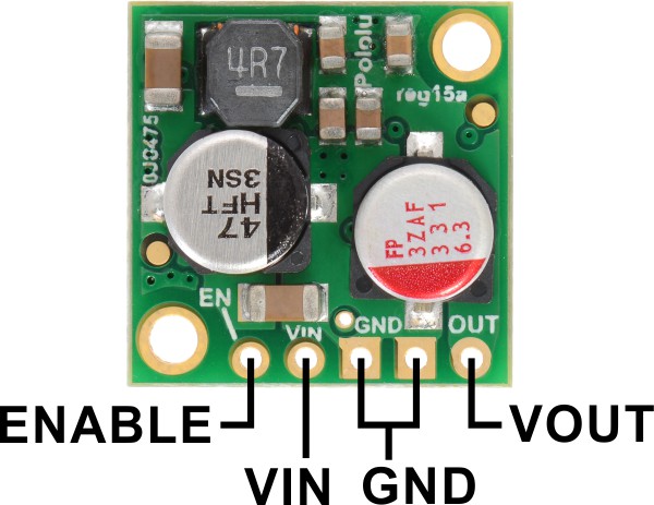
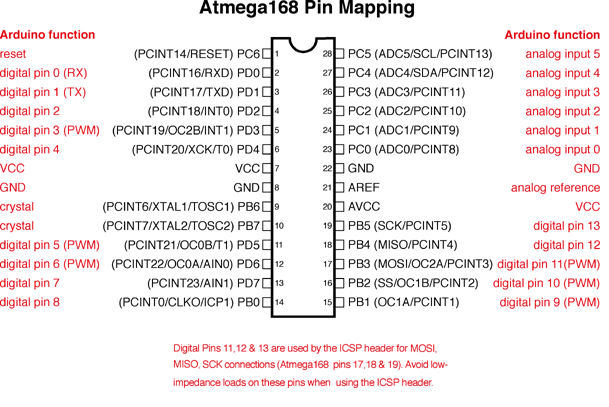
| Item | Url |
|---|---|
| Firmware Update Guide | https://www.silabs.com/documents/login/user-guides/UG216.pdf |
| Page containing firmware | https://www.silabs.com/documents/login/data-sheets/WT32i-DataSheet.pdf |
| Link to firmware zip file | https://www.silabs.com/documents/login/software/iWRAP-Firmware-Releases.zip |
| Prolific PL2303 USB driver | http://www.prolific.com.tw/US/ShowProduct.aspx?p_id=225&pcid=41 |
| FTDI USB driver | http://www.ftdichip.com/FTDrivers.htm |
The following things are verified before packing and shipping a BlueGigaEmpeg:
- BetzTechnik board upgraded to version 6.2.0 build 1122.
- BetzTechnik board power switch is in the down/off position.
- Jumpers on BlueGigaEmpeg board are set to the "crossover" configuration.
- Arduino contains current version of Github code, check version at bootup.
- Arduino displays good serial buffers, check messages at bootup.
- WT32i reports version "(6.2.0 build 1122)" when booted.
- Powering up empeg displays a message on debug console (empeg messages work).
- Pairing button and LED works, pairing mode pairs with the playback device.
- Play/pause works on Bluetooth playback device (AVRCP+empeg commands work).
- Audio playback quality is good.
- Touch-check for no hot components after playing music for a few minutes.
- LED is straight.
- Place assembly into enclosure, make sure fit is perfect, LED is in the hole.
- Make sure pair button works with the enclosure closed up.
- Screw in the enclosure bolts slowly, and in three stages, to prevent heat stripping.
- Can remove and reinsert enclosure bolts without stripping the plastic.
- Box includes baggie with USB cable, jumper wires, stickers, shrink tubing.
- Printout of one-pager instruction sheet is included in the box.